ESDEP WG 1B:
STEEL CONSTRUCTION:
INTRODUCTION TO DESIGN
To discuss structural arrangements in multi-storey buildings with particular reference to resisting lateral loads.
An understanding of design philosophies, structural arrangements and static and dynamic structural analysis.
Lecture 1B.1: Process of Design
Lecture 1B.2.1 : Design Philosophies
Lecture 1B.2.2 : Limit State Design Philosophy and Partial Safety Factors
Lecture 1B.3 : Background to Loadings
Lectures 1B.4 : Historical Development
Lecture 14.8: Classification of Multi-Storey Frames
Lecture 14.9: Methods of Analysis for Multi-Storey Frames
Lecture 14.10: Simple Braced Non-Sway Multi-Storey Buildings
Lecture 14.14: Methods of Analysis of Rigid Jointed Frames
This lecture discusses different structural systems (shear frame, shear truss-frame, steel-concrete, tube, etc.). Particular comment is made with regard to ultra high-rise buildings and seismic effects.
The use of structural steels in the last century permitted a great increase in the height of building constructions leading to modern high-rise buildings.
For low-rise buildings the most common structural solution is obtained by integrating two different load resisting systems in the same structure:
By means of the so-called 'fourth dimension of steel construction' (which introduces, besides the three geometrical dimensions, the range of available material strength), it is possible to unify the cross-sections of members and, therefore, to obtain optimum and economic solutions for a range of building forms.
For high-rise buildings (up to 120 storeys), different structural systems are used according to the height range:
For 'braced' steel frames, different types of bracing can be used according to the structural and functional requirements.
Appropriate calculation models for multi-storey buildings can be used for pin-ended structures and truss bracings.
For seismic resistant steel structures, an excellent performance in terms of strength and ductility can be obtained. The design requirements in such cases correspond to three given limit states: serviceability, resistance to damage, and prevention of collapse.
In the last hundred years man has accepted the challenge to increase the size of multi-storey buildings. Height has been increased successfully thanks to the use of structural steels which give suitable mechanical properties in terms of strength and ductility.
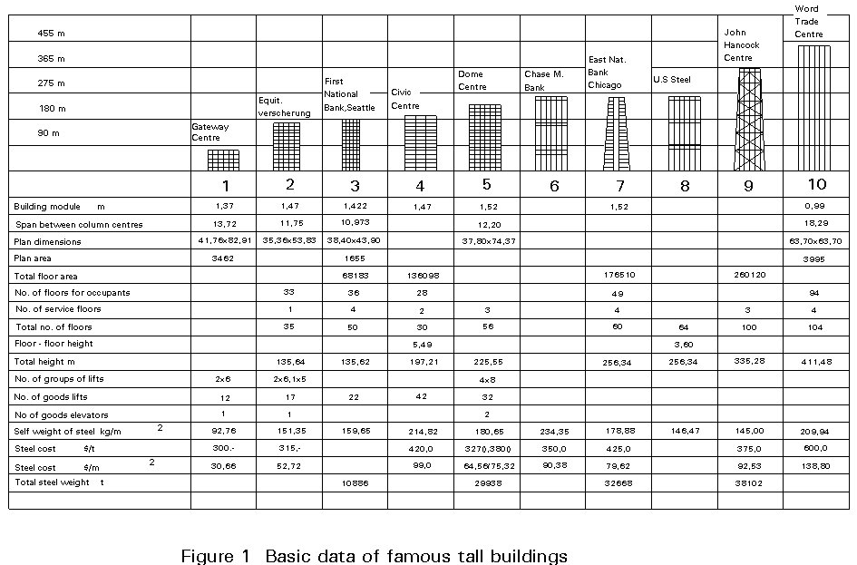
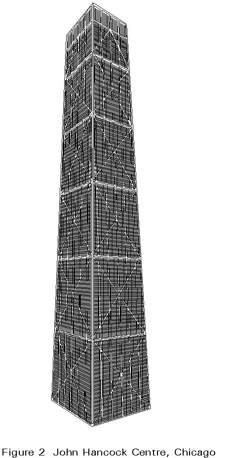
The resulting range of buildings extends from multi-storey buildings to tall buildings, and to 'skyscrapers'. The increase in height is gradually changing the skyline of many cities (Figure 1). The development of taller buildings has stimulated the creation of new structural systems, which are more able to provide the increasing resistance needed due to the effects of height. The dynamic action of wind is no longer negligible as the number of storeys increases and becomes as important as the horizontal seismic actions due to earthquakes. Examples of this situation may be found in the high-rise buildings of the United States. In 1965 the John Hancock Center in Chicago was considered the tallest building in the world with 100 storeys and 335m height (Figure 2), excluding the traditional Empire State Building in New York built in 1931 using the structural engineering practice of the time. The innovative structural system of the John Hancock Center consists of a bearing structure around the perimeter which behaves as a framed and diagonal tube.
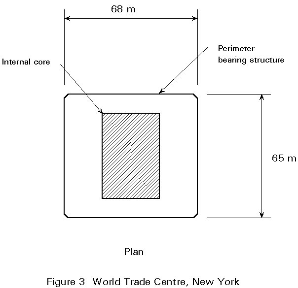
From 1970, the erection of the twin towers of the World Trade Center in New York commenced which surpassed in height, both the John Hancock Center and the Empire State Building. The twin towers have a square plan and their structural system is called a 'tube in tube', because it is made of an external skin with very close steel columns (framed tube) and an internal core where all vertical facilities are concentrated (stairs, elevators and so on). This concept allowed the building to reach 104 storeys and 411 metres of height (Figure 3).
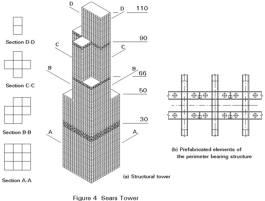
The supremacy in height of the John Hancock Center was of very short duration. In 1974 the 'Sears Tower' in Chicago became the tallest building in the world, it being 110 storeys and 442m in height (Figure 4a). Its structural system consists of an external framed tube located on the perimeter together with three horizontal trusses, which act as ring belts. A feature of the building is the reduction of its plan area with the height, which transforms the base square into a quasi-rhombic shape, a cross shape and finally a rectangular shape at the top of the building. The variation of the resisting cross-section makes this structure similar to a big cantilever with variable section. It is interesting to observe that the perimeter structure is made of completely prefabricated elements of three spans and two storeys in height which characterise the facade (Figure 4b).
The Sears Tower has now been passed by the Petronas Towers in Kuala Lumpar at 452m and will also be passed in 2001 by the World Financial Centre, Shanghai at 460m. In the last twenty years, many types of multi-storey and high-rise buildings have been erected not only in the USA, but also in Europe and Japan.
The simplest way to resist both vertical and horizontal loads is to use moment resisting frames (cases 1 and 5 of Figure 5), with floor structures oriented in transverse and longitudinal directions, respectively. This solution is not rational, and therefore not the most economical, because it requires beams and columns with different cross-sections at the various levels. In addition, it is susceptible to too large sway deflections when the number of storeys is greater than 4 or 5.
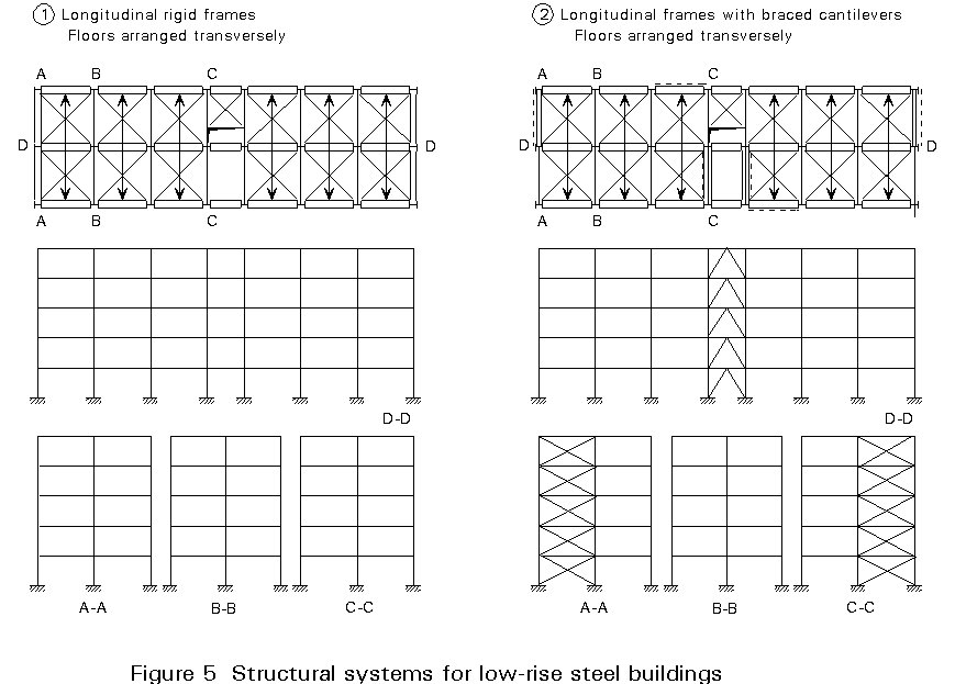
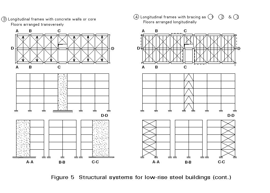
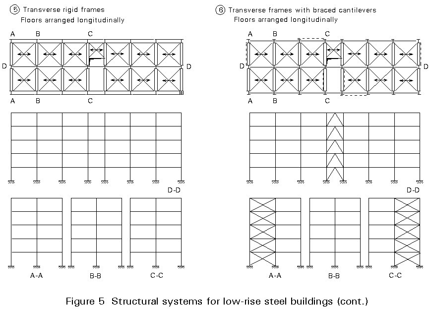
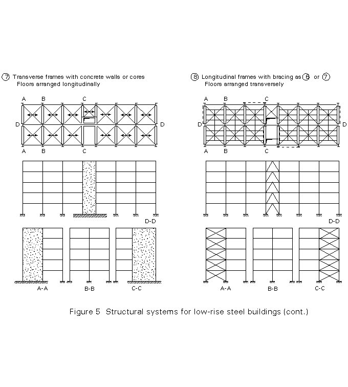
A better solution is obtained by the use of two different structural systems in the same building (cases 2, 3, 4, 6, 7, 8 of Figure 5), i.e.:-
Both systems are connected together by means of floor structures, which provide a rigid diaphragm at each storey level. The main advantage of this solution is that it makes it possible to unify the shapes of all beams independently of the floor level.
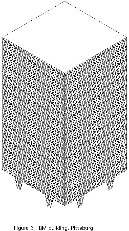
The unification of column sections is also possible, provided that different grades of steel are used (S235, S275, S355) according to the magnitude of stress in the columns. This use of different steel grades is commonly called 'the fourth dimension of steel construction', because it allows, in addition to the three geometrical dimensions, the adjustment of the steel strength in order to optimise the working conditions of the structural members. The unification of the shape of the structural elements is a fundamental pre-requisite for reducing the costs of fabrication and erection.
The first example of the use of the 'fourth dimensions of steel construction' was the IBM Building in Pittsburgh, built in 1965 with three different kinds of steel for the bars of the external lattice bracing, (Figure 6).
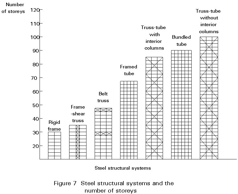
The structural system of a high-rise building must resist both gravity and lateral loads, due to phenomena such as wind and earthquake. As the height of the building increases, the lateral loads gradually dominate the structural design.
Figure 7 systematically compares some frequently used steel structural systems on the basis of the structural efficiency, which is measured by the weight of the building [1]. Framed tube structures could be conveniently used in high-rise buildings up to 20 storeys.
Lateral loads due to wind and earthquake produce lateral accelerations. As people normally perceive these accelerations during service conditions, stiffness rather than strength tends to become the dominant factor in buildings of great height. The serviceability limit state can, therefore, be more important than the ultimate limit state.
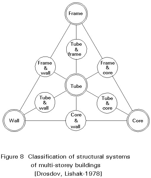
Four overall groupings of structural systems may be identified (Figure 8). They are:
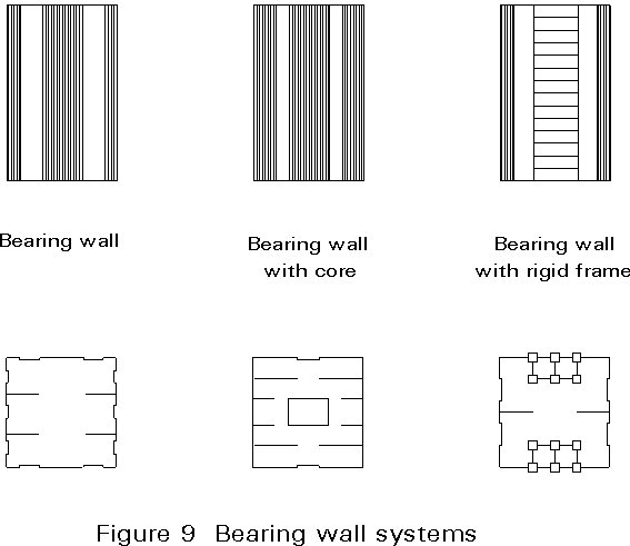
a. bearing wall system
b. core system
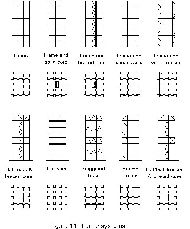
c. frame system
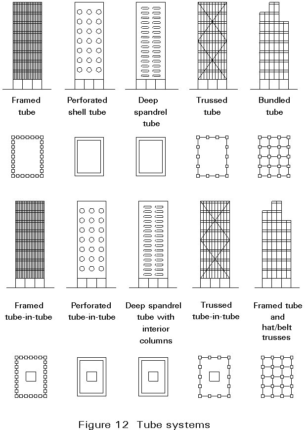
d. tube system.
Each system has different lateral load resisting properties and thus tends to be 'efficient' over a different height range.
The bearing wall system due to the self weight of the structural components (usually concrete), normally becomes inefficient for buildings above 15-30 storeys in height.
The concrete core system has the same disadvantage as the bearing wall system, namely self weight is a limiting factor.
The efficiency of the framed system depends upon the rigidity of the connections and the amount of bracing. Stiffening can be achieved by use of a solid core, shear walls or diagonal bracing. As more bracing is incorporated into the spatial frame, the range of efficient height is increased. The upper limit is in the range of 60 storeys.
The tube system can be thought of as a spatial frame with the vertical elements positioned at the exterior. The range of height efficiency is influenced by the type and the amount of bracing employed in the tube. In general a tube structure is considered the most efficient form for the tallest buildings, i.e. above 60 storeys in height.
From the four basic structural systems, six secondary systems can be derived from a combination of the basic ones (see Figure 8).
The four basic systems are assumed as the prime groups which can be associated to the levels of the structural system hierarchy as proposed by Falconer and Beedle. These primary systems are:-
Wall structures as well as cores are usually made of reinforced concrete.
Steel frames can be used together with concrete cores, and/or walls, leading to composite structures, which may be called also 'dual structures'.
When steel frames are braced, different types of bracing can be used according to structural and functional requirements (Figure 13).
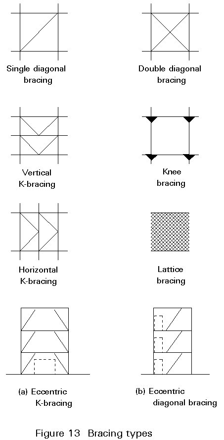
The most common are:
Both K- and single diagonal bracings can be 'eccentric', i.e. the diagonal members do not meet in the nodes.
In the design of multi-storey buildings it is usual to refer to a calculation model, which corresponds to an ideal structure having perfect constraints. In contrast, the actual construction details show that the connections between the various members which comprise the structure are considerably different from the assumed idealisations. It is therefore important to point out that any approach to structural design must be based on simplified hypotheses and schemes which make the correlation between the actual structure and model possible. Only the model can be studied by the methods of structural analysis. The results of the analysis will more closely predict the actual behaviour of the structure, the nearer the model represents the structure itself.
A question to ask is whether the introduction of simplifying hypotheses leads to a model whose behaviour is on the safe side or not. It is necessary to check whether the results obtained from the model and, in particular, the ultimate load carrying resistance at collapse, are safe or unsafe.
To answer this question it may be helpful to apply the basic design static theorem. In a structure subject to a set of external forces Fj, auFj are the values of the loads that, if applied, would produce the collapse of the structure, au being the actual collapse multiplier. If, for a generic load aFj it is possible to find a distribution of internal forces which balances the external forces, and if the structure also complies everywhere with a given plasticity criterion, then a £ au.
This theorem is valid if the following hypotheses are satisfied:
A calculation model will be able, therefore, to predict actual behaviour more nearly as the compatibility conditions are more strictly satisfied.
Any solution is however on the safe side, even though compatibility is not complied with, provided that:
Clearly, once the calculation model has been defined, the stability of members must be checked and, in the case of highly deformable structures, the influence of second order effects on vertical loads must be assessed. Some typical examples of calculation models of steel structures are described below.
The model of a generic pin-ended structure (Figure 14) can be studied with reference to various positions of the ideal hinges. They can be located, for example, in any one of the three positions shown in Figure 14. Results will be on the safe side provided the dimensions of the various structural elements comply with the assumed model. From the three cases shown, the following criteria can be deduced for calculating the moments and forces in the columns, beams and connections (sections X-X and Y-Y).
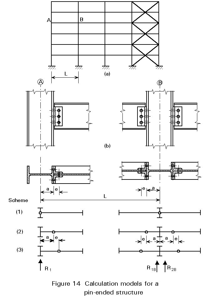
Scheme 1
Columns A and B are simply compressed.
L is the span for calculating the beam moment.
The joint section X-X must resist not only a shear force V = R1, but also a moment M = R1a.
The joint section Y-Y must resist not only a shear force V = R1, but also a moment M = R1 (a + e).
Scheme 2
Column B is compressed (N = R1B + R2B) and subject to a moment M = a (R1B -R2B) concentrated at the central axis.
Column A is compressed (N = R1) and subject to a moment M = R1 a concentrated at the central axis.
L - 2a is the span for calculating the beam moments.
The joint section X-X must resist a shear force V = R1 only.
The joint section Y-Y must resist not only a shear force V = R1, but also a moment M = R1e.
Scheme 3
Column B is compressed (N = R1B + R2B) and subject to a moment M=(R1B -R2B) (a + e) concentrated at the central axis.
Column A is compressed (N = R1) and bent by a moment M = R1 (a + e) concentrated at the central axis.
L - 2 (a + e) is the span for calculating the beam moments.
The joint section X - X must resist a shear force V = R1 and a moment M = R1e.
The joint section Y - Y must resist a shear force V = R1 only.
Each of these three models is on the safe side and can therefore be assumed for calculation. The choice between them is made considering the structural element or the joint which is the weakest part of the structure. The model which minimises the internal forces in that part is chosen, because it is the most safe.
In the first scheme the state of stress in the column is the lowest. It can, therefore, be chosen when columns are oriented according to their weak axis (Figure 15a). Bending effects in the columns are, in fact, eliminated in spite of slight moments in the joints due to a relatively small eccentricity of the bolted connection.
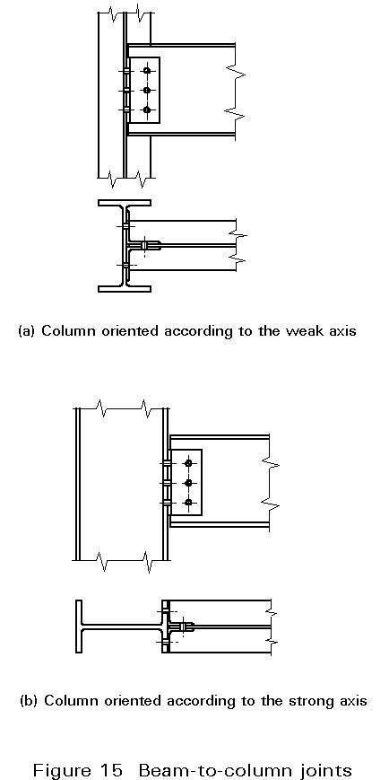
The second scheme is often conservative if the columns are oriented according to the strong axis (Figure 15b). In this case, in fact, eccentricity is greater than half the column depth and it could require an increase in the resistance of the connection. The eccentricity also entails a greater stress in the columns due to bending moments. Their distribution can be evaluated by assuming hinges at the mid-point between floors and by considering the columns fixed by the bracing structure (Figure 16a). Thus, each vertical row can be considered by means of the isostatic scheme shown in Figure 16b. The horizontal reaction Hi is given by rotational equilibrium around the hinge number i:
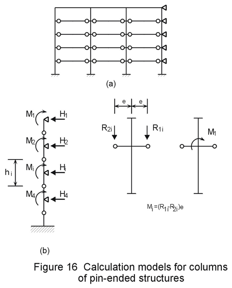
Hi = ![]()
The effects of forces Hi, for each floor and for each column, are resisted by vertical bracings through the floor system. Their intensity is approximately DR e/h, wherein DR is the difference between the reactions of two beams connected at the column and e/h is the ratio between the hinge eccentricity and the floor height. In the types of structure being considered, as the beam spans are comparable, DR depends mainly on any unbalanced accidental loads. Furthermore, as e/h is essentially small, these effects are generally negligible compared with those due to external loads. In contrast, bending moment effects on the columns are not negligible. The corresponding increase in stress must be considered in the calculations.
Forces acting on bracing structures, such as the effects of wind, earthquakes and geometric imperfections, do not act in a particular direction. Therefore, the scheme of a bracing system has to be designed and calculated for a range of loading conditions.
Referring to the simple truss bracing shown in Figure 17a, the behaviour of a single diagonal system is considered (Figure 17b).
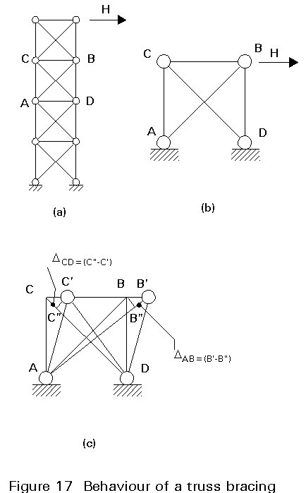
The structure is hyperstatic. Its solution to determine sway displacements is determined by the compatibility condition (Figure 17c), assuming member ![]() as rigid. This assumption imposes the equality DAB = DCD between the elongation of the tension diagonal AB and the shortening of the compression diagonal CD. If the N-D relationship between the axial load N and variation D in the length (Figure 18a) is equal in both tension and compression, then the axial force in both diagonals has the same absolute value. The structure can be considered as the superposition of two isostatic structures working in parallel (Figure 18b) and its solution is straightforward.
as rigid. This assumption imposes the equality DAB = DCD between the elongation of the tension diagonal AB and the shortening of the compression diagonal CD. If the N-D relationship between the axial load N and variation D in the length (Figure 18a) is equal in both tension and compression, then the axial force in both diagonals has the same absolute value. The structure can be considered as the superposition of two isostatic structures working in parallel (Figure 18b) and its solution is straightforward.
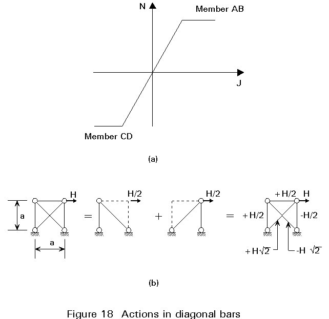
The diagonals, however, differ substantially in their behaviour. The compressed bar CD may not have a linear behaviour because, although it remains elastic, it is subjected to buckling and the variation from linear behaviour increases as its slenderness l increases (Figure 19a). For high slenderness (Figure 19b), the geometric condition DAB = DCD requires an axial load Nc in the strut which is substantially lower than the axial load Ni in the tie.
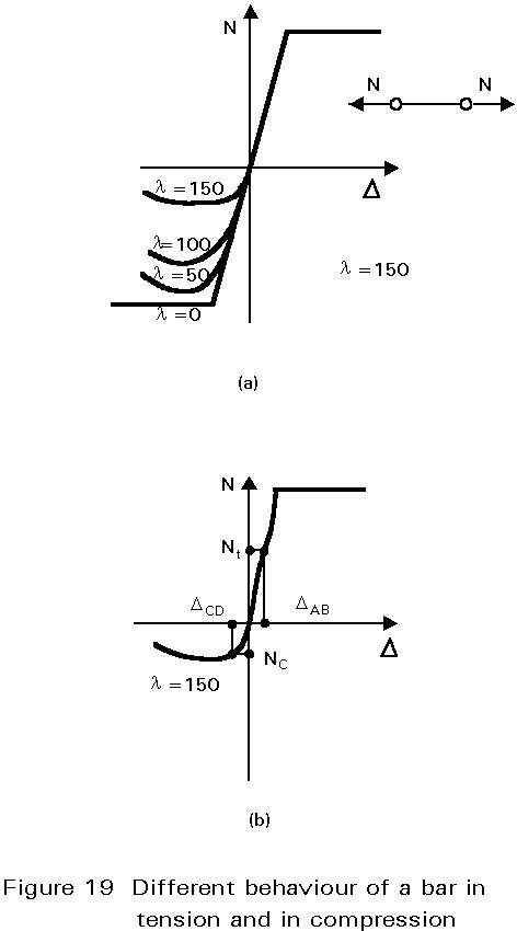
There are, therefore, two ways of dealing with bracing. It can be dimensioned so that both diagonals can resist both tension and compression. For this purpose a low slenderness is required (l £ 100), so that the difference in behaviour between tension and compression bars is negligible. This solution is illustrated in Figure 18b: both diagonals cooperate in resisting shear forces. Alternatively, the bracing can be dimensioned by considering the tension diagonal alone. High slenderness is required (l ³ 200) in order to ensure that, when the stress reverses and the diagonal becomes a strut, it will remain elastic even if it buckles. Under this condition the bar in compression is redundant and the forces are wholly resisted by the tension bar. Bracings designed in this way are generally more economical, but deformation of the structure is greater. Furthermore, the possibility of buckling of compression diagonals makes this solution inadvisable whenever the bracing is located in the plane of facades or partition walls.
The above considerations are applicable also to other types of bracings.
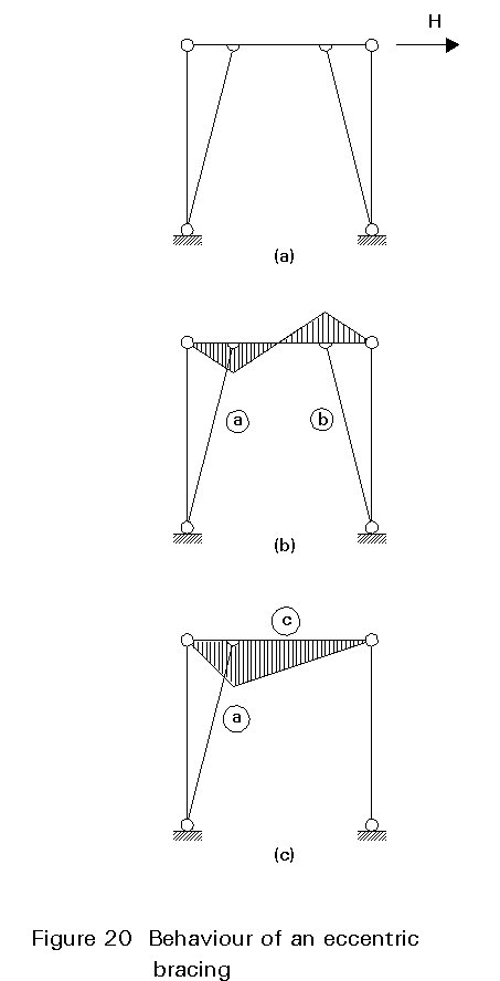
The bracing shown in Figure 20a, for example, consists of two inclined bars connected to a beam which resists bending. The beam can be calculated by the method indicated in Figure 20b or by that of Figure 20c, according to whether the compression bar is taken into consideration or not. The bracing in Figure 20b, corresponds to members of a truss bearing axial loads only. One diagonal member is one in tension and one in compression. As both members are identical, a check must be made that they can satisfactorily resist the compressive load. In Figure 20c only the tension bar is considered operative. Consequently the beam must also resist bending due to the external force H. In this case also the bracing can be economical, provided the compression bar is sufficiently slender to buckle whilst remaining elastic.
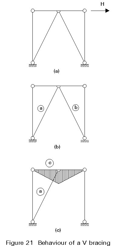
The same approach can be followed for the bracing system shown in Figure 21a. In Figure 21a the bracing bars are designed to act in both tension and compression. This design minimises bending in the beam. Alternatively, in Figure 21c the bracing is designed to take tension only, the member in compression being ignored. This design increases bending in the beam.
Multi-storey steel buildings are used more and more extensively in regions of high seismic risk because of their excellent performance in terms of strength and ductility. Their performance is due to the mechanical behaviour of materials, structural elements and non-structural components, which is required by the design. The design requirements correspond to the imposition of three given limit states. They are the serviceability, resistance to damage (damageability) and collapse limit states which are included in the new generation of seismic codes, such as the ECCS Recommendations for Steel Structures in Seismic Zones [2] and the Eurocode 8 [3].
The serviceability limit state corresponds to minor frequent earthquakes. It requires that the structure together with the non-structural components should suffer no damage and that discomfort to the inhabitants should be minimal. The first requirement (to avoid structural damage) is fulfilled by designing the structure in elastic range. The second requirement (to avoid non-structural damage and inhabitants' discomfort) is obtained by providing sufficient stiffness to prevent significant deformations.
The "damageability" limit state allows some minor damage to non-structural components due to local large deformations in certain zones. Such damage may occur under less frequent moderate earthquakes.
The collapse limit state is related to severe ground motions due to very infrequent earthquakes. Both structural and non-structural damage is expected, but the safety of the inhabitants has to be guaranteed. The structure must be able to absorb and dissipate large amounts of energy. Different ways can be used to absorb and dissipate energy under very strong ground motions in order to prevent collapse.
Traditionally, two families of structural systems have been used in multi-storey buildings to resist important horizontal loads (both wind and earthquakes). They are the concentrically braced frames and the moment-resisting frames.
The concentrically braced frame system is widely used both for normal and seismic-resistant steel structures. Vertical cantilever trusses are formed by diagonal bracing elements with coincident centrelines. They resist lateral forces (both winds and horizontal earthquakes) by means of axial forces in the bracing elements, leading to a large stiffness in the elastic range. In these structures the dissipative zones are mainly located in the tensile diagonals, because it is usually assumed that the compression diagonals are buckled.
The inelastic cyclic performance of concentric bracings is rather unsatisfactory due to the repeated buckling of the diagonal members. This buckling produces a progressive reduction of the area of the hysteresis loops, which corresponds to a significant decrease in the capability of the structure to absorb and dissipate energy. This behaviour is illustrated by the shape of the hysteresis loops of a concentric bracing (Figure 22).

Different behaviour arises according to the type of bracing. The types can be classified into three categories: diagonal X-bracings (Figure 23a, b, c), V-bracings (Figure 23d, e, f) and K-bracings (Figure 23g). The X-bracings (Figure 23a) dissipate energy by means of the plastification of both compression and tension diagonals and the degradation is due to out-of-plane buckling, which interacts with local buckling of the cross-section. From this point of view, symmetrical sections (double C, hollow sections) exhibit a better performance than unsymmetrical ones (back-to-back angles). In the V-bracings, the horizontal forces are resisted by both tension and compression diagonals, the last being necessary for equilibrium. From the cyclic loading point of view, only the compression diagonal dissipates energy, whereas the tension diagonal remains elastic.
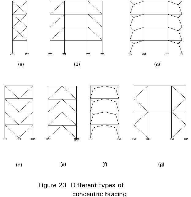
K-bracings (Figure 23g), on the contrary, cannot be considered as dissipative because the diagonals intersect the column in an intermediate point, thereby including the column in the yielding mechanism.
In summary, for all types of concentrically braced frames, unacceptable large interstorey drifts causing non-structural damage can occur due to the failure of bracings.
The moment-resisting frames have a large number of dissipative zones which are located near to the beam-to-column connections. They resist horizontal forces essentially by bending and energy can be dissipated by means of cyclic bending behaviour.
Beam-to-column connections are usually designed according to the four main types of joints (Figure 24):
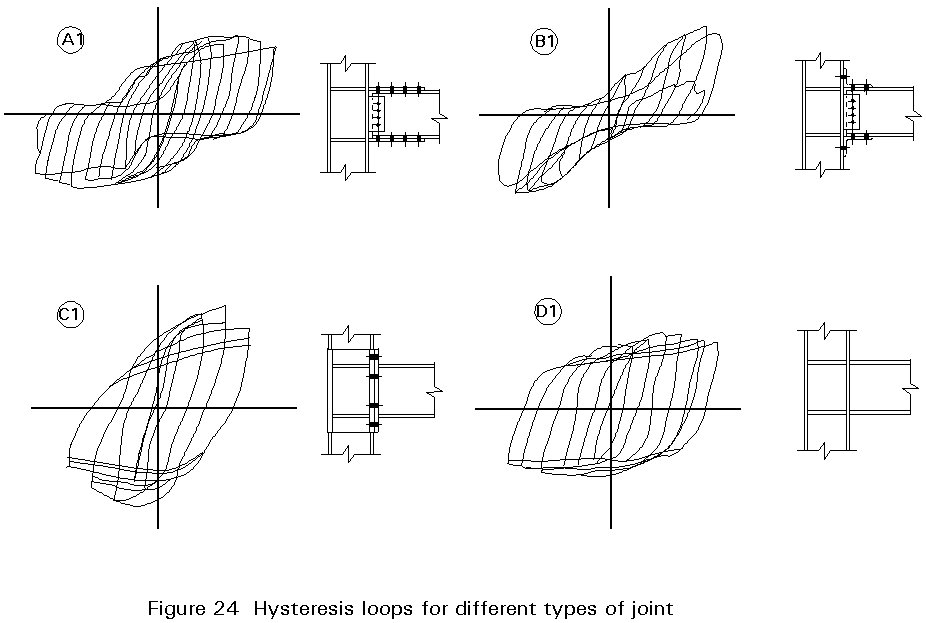
Type A, where three plate splices are welded to the column and bolted to the flanges and to the web of the beam.
Type B, where angle splices are bolted both to the column and to the beam.
Type C, with end plate joint with symmetrical extension.
Type D, which is a fully welded joint.
The performance of all types has been found by testing to exhibit sufficient ductility.
Moment resisting frames are widely used for low-rise buildings, but they are generally more expensive than the concentrically braced system for a given height. For medium and high-rise buildings (from 6 to 40 storeys) framed structures exhibit too large elastic deformations under the action of low earthquakes or wind, producing damage to non-structural elements. Sufficient stiffness can be obtained by adding diagonal bracings to the rigid frame.
From a comparison between the behaviour of concentrically braced and moment-resisting frames, it is concluded that neither of these two traditional systems fulfil contemporary requirements for the three limit states: serviceability, damageability and collapse.
A suitable harmonisation between the lateral rigidity of bracings and the ductility of frames can be obtained using the hybrid framing system of eccentrically braced frames (Figure 25). In this system the horizontal forces are resisted mainly by axially loaded members, but the eccentricity of the layout allows the energy dissipation by means of cyclic bending and shear behaviour in an element known as an active link.
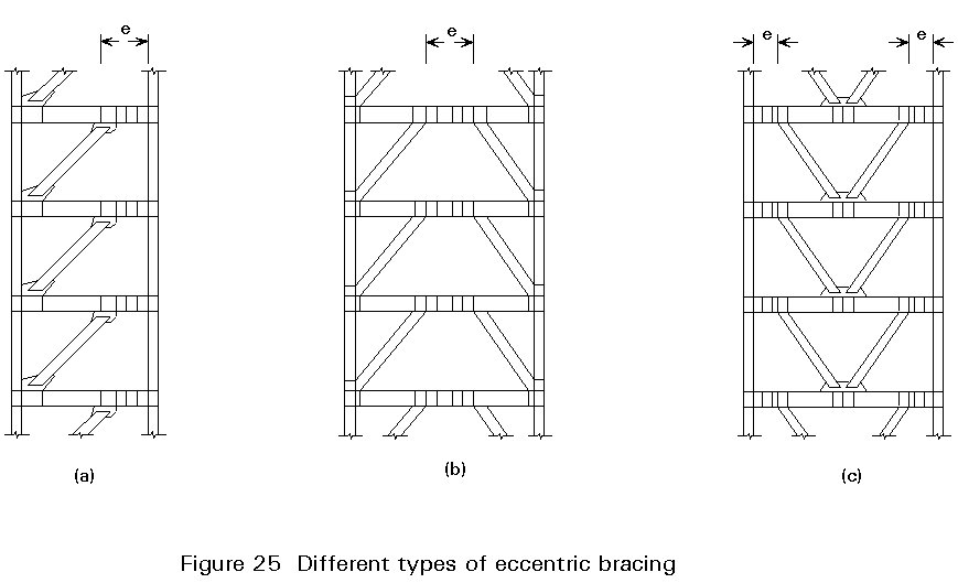
The common type of eccentrically braced frame can be classified as D-brace (Figure 25a), K-brace (Figure 25b) and V-brace (Figure 25c) according to the shape of the diagonal elements. Eccentrically braced frames belong to the group of dissipative structures and their level of energy absorption is similar to the moment-resisting frame system.
In addition, the eccentrically braced frame system has advantages in terms of drift control. It provides an economic solution in the range of medium and high-rise buildings. The active link is the main energy dissipator in the structural system. It must be designed so that its bending and shear limit strength is reached prior to the attainment of tension and compression limit strengths of other bars.
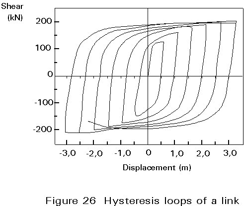
The length of the active link is responsible for the collapse mechanism which dissipates energy. The short links dissipate energy mainly by inelastic shear deformation in the web (shear link). The long links dissipate energy mainly by inelastic normal strains in the flanges (moment links). A careful design of these links can lead to very satisfactory hysteresis loops with high energy absorption, while maintaining satisfactory rigidity (Figure 26).
Eccentrically braced frames meet the requirements of all three limit states which the seismic design of steel structures considers. In particular they provide excellent strength and rigidity in the elastic range so that non-structural damage and occupant discomfort are avoided. They also have enough ductility to dissipate large amounts of energy in the inelastic range.
[1] New Structural Systems for Tall Buildings and Their Scale Effects on Cities, Khan, Fazlur R. "Tall Building Plan, Design and Construction", Symp, Proc, Vanderbilt University, Civ Eng Program, Nashville, Tennessee, 1974.
[2] Eurocode Convention of Constructional Steelwork : "Recommendations For Steel Structures in Seismic Zones", ECCS, Publication 54, 1988.
[3] Eurocode 8 : "Structures in Seismic Regions - Design", CEN (in preparation).
Blackwell Scientific Publications, Oxford. 1992