ESDEP WG 14
STRUCTURAL SYSTEMS: BUILDINGS
To describe less known forms of single storey steel structures, including cable and tension structures.
None
Lecture 14.5: Space Structure Systems
Lecture 15C.4: Guyed Masts
The lecture examines some less-common structural systems, not described earlier. Variants on standard forms used for industrial buildings are briefly described. Cable-stayed and tension structures are described in more detail.
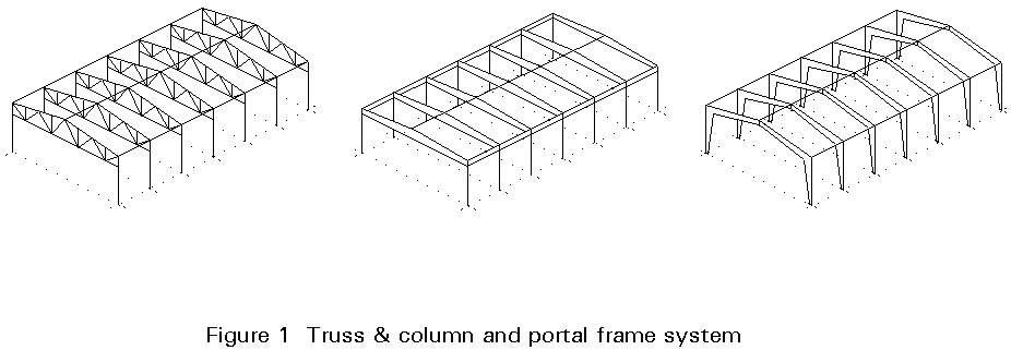
Most single storey structures are portal or trussed frames, Figure 1. These structural forms have been shown to provide economic and effective solutions for routine construction. However, alongside these commonplace forms a wide range of single storey structures have been developed for special applications.
Although the number of special structures is relatively small, they encompass a wide range of structural forms. Many of these structures result from the need to cover large areas, typically for sports, exhibition, industrial or commercial purposes. As such, they are characterised by large uninterrupted spans and relatively light imposed loading. They are frequently lightweight, reflecting their designers' intention to maximise structural efficiency. Structural considerations are, therefore, to the fore in determining their architectural form.
The lightness of these structures requires close attention to be paid to aspects of structural action and response that are not significant for more conventional structures. Attention has to be given to dynamic and fatigue effects, to load reversal and to uplift. In this latter regard, elements primarily designed for tension may need to be braced to resist compressive forces, and elements may require pretensioning to ensure that stiffness is maintained under reversible or dynamic loading. Members and connections may require detailing for fatigue. Temperature effects and second order effects relating to cable extension or relaxation may also need to be considered.
It is convenient to categorise these forms in terms of their structural systems. These include direct-force systems and mixed systems combining flexural elements with major direct-force components, in addition to systems which exploit the potential of curved or folded forms. In some cases, the foundations play a more complex role than usual in equilibrating the force system and in limiting deformations.
It is proposed in this lecture to outline some of the more common systems encountered. Additional material on some of these topics will be found in Lecture 14.5 on Space Frames, and Lecture 15C.4 on Guyed Masts and Towers. The slides on special single-storey structures provide a wide range of examples of the application of the principles outlined in this Lecture.
The Lecture commenced with a brief review of some non standard approaches which have been used for industrial buildings in the past - the saw tooth roof, the umbrella and butterfly roof and the arch roof. The dome is also reviewed.
With large-span structures, the consequences of failure are more likely to be catastrophic than is the case for normal structures and safety therefore merits particularly careful consideration at all stages of the life of the structure. The more severe consequences of failure can be attributed partly to the large scale and partly to the lack of structural redundancy encountered in many of the systems adopted for large-span structures. Increased redundancy offers the prospect of greater stiffness and strength, and the alternative load paths associated with redundancy offer a reduced likelihood of total collapse. Against this must be balanced the capacity of statically determinate structures to accommodate secondary effects (shrinkage, creep, relaxation, temperature changes, settlement, lack of fit, etc.) without distress.
Special structures require critical assessment of the applicability of standard loading codes, particularly in regard to wind. Construction techniques, materials and detailing may be non-conventional and introduce additional uncertainties. Non-linear effects - relating to material or geometrical factors - may have a bearing on the behaviour and detailing of the structure. Inspection during construction, and periodic inspection and maintenance of the structure in service, assume added importance.
Some of the more interesting types of older, single-storey steel structures are briefly described below. These types have been used extensively in the past, and although their use today is rather limited because of the development of other systems, they still have a significant interest for the designer. In certain cases they can still provide satisfactory solutions from the viewpoints of functionality, economy and aesthetics.
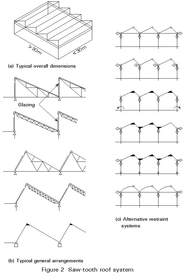
This structural system (Figure 2) was frequently used in the past, mainly for industrial buildings. Its use is now rather limited because its main advantage of uniform daylighting into the building, is achieved by new roofing products that can provide daylighting efficiently through flat roofs, or by artificial lighting. The saw-tooth roof is costly to construct, wasteful of heat, and requires many internal gutters.
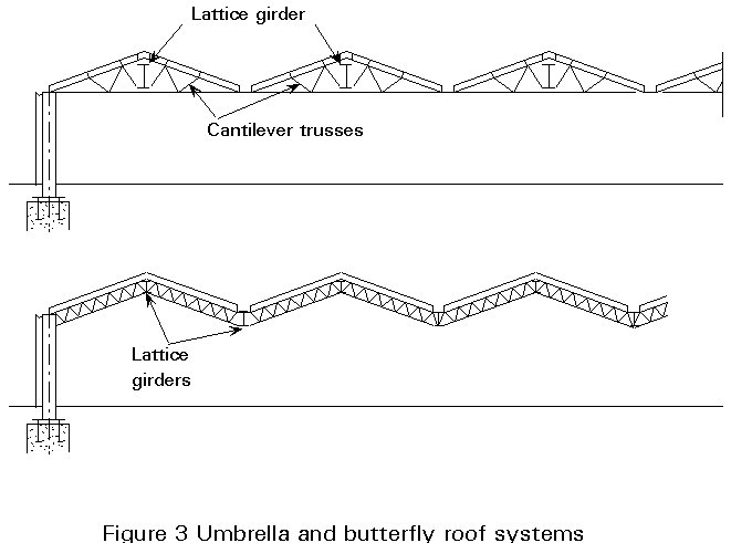
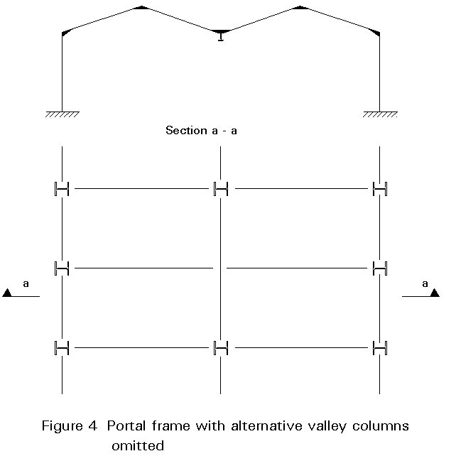
These two structural systems (Figure 3) are conceptually very similar to the saw-tooth roof, and they are used to cover large floor areas with a minimum of internal columns. It is still common to use this construction in portal frames with, for example, alternate valley columns omitted (Figure 4).
Arches have long been recognized as being highly efficient and economic structural systems for covering large spans in buildings (Figure 5).
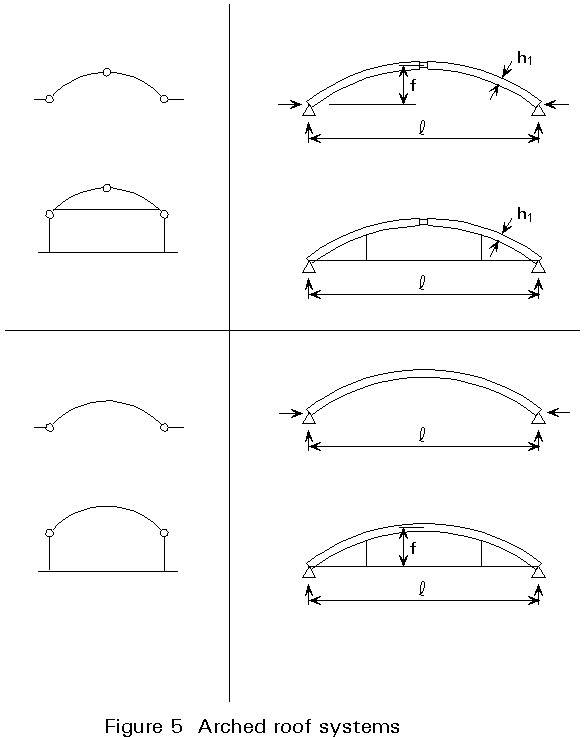
The main problem of an arch is the thrust developed at its supports. The thrust can be of considerable magnitude for long spans. It increases as the ratio of rise to span becomes smaller and can be resisted only by appropriate foundations, or by an arch tie.
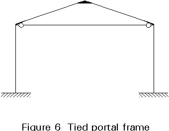
Portal frames benefit from arching action, which has led to the use of tied frames (Figure 6). Care has to be taken to design the rafter against the considerable compressive force that arises. Also the tie member must not buckle if wind uplift causes reversal of force in this member.
Prestressing provides an option, if uncommon, for creating a more favourable regime of bending moments in large span frames, as well as for deflection control (Figure 7).
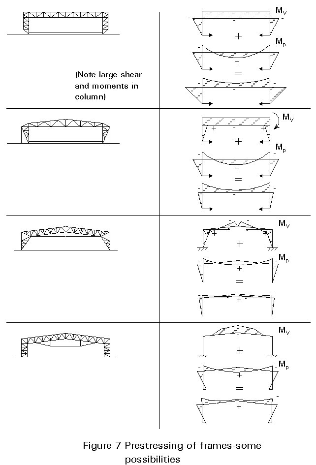
The additional compressive forces must obviously be taken into consideration in determining the bracing requirements of members.
Domes are three-dimensional structures used to cover buildings with a circular floor plan. Their cross-section may be spherical, elliptical, parabolic, etc.
Steel framed domes have been extensively used for public assembly buildings such as auditoria, arenas, gymnasia, exhibition halls, etc.
There are many types of dome (Figure 8). A common type is the ribbed spherical dome which consists of main meridional ribs and horizontal (parallel) rings. The rings decrease in diameter going from the base to the top of the dome, concluding with the compression ring at the top. This arrangement, whereby the ribs are stopped at the compression ring instead of being continuous over the pole, is used practically in all dome designs. It has three advantages. Firstly, it makes possible the connection of all ribs converging to the same point. Secondly, a large opening is formed which can be used for lighting and ventilation. Thirdly, the structure becomes statically determinate.
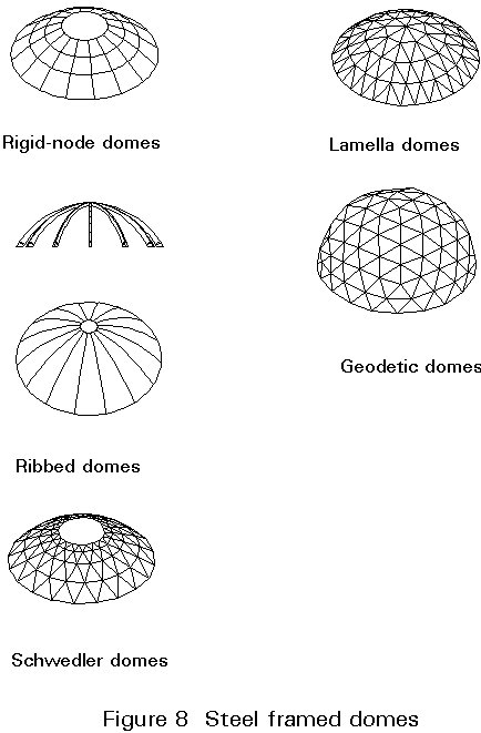
Apart from the compression ring at the top, the primary system of ribs and rings, may be subjected to further modifications. For example, auxiliary members, such as purlins and diagonal bracings may be added in the plane of the roof surface. The bracings are usually placed in alternate bays. They are an important aid during erection, which is usually done by using only one scaffold tower at the centre of the dome.
Another modification concerns the connections between the ribs and rings. Theoretically they should be pinned but in practice they are moment resisting. Finally, the geometry of the dome is usually modified, so that only the panel points lie on the true spherical surface. All members between these points are made straight, resulting in considerable fabrication savings.
This type of dome is essentially a direct force structure, its individual members being subjected primarily to axial tension or compression (membrane action).
For symmetrical loading, the global analysis can be made by simple statics (Figure 9). However this method is invalid for analysis under unsymmetrical loading. The most important unsymmetrical loading is wind pressure.
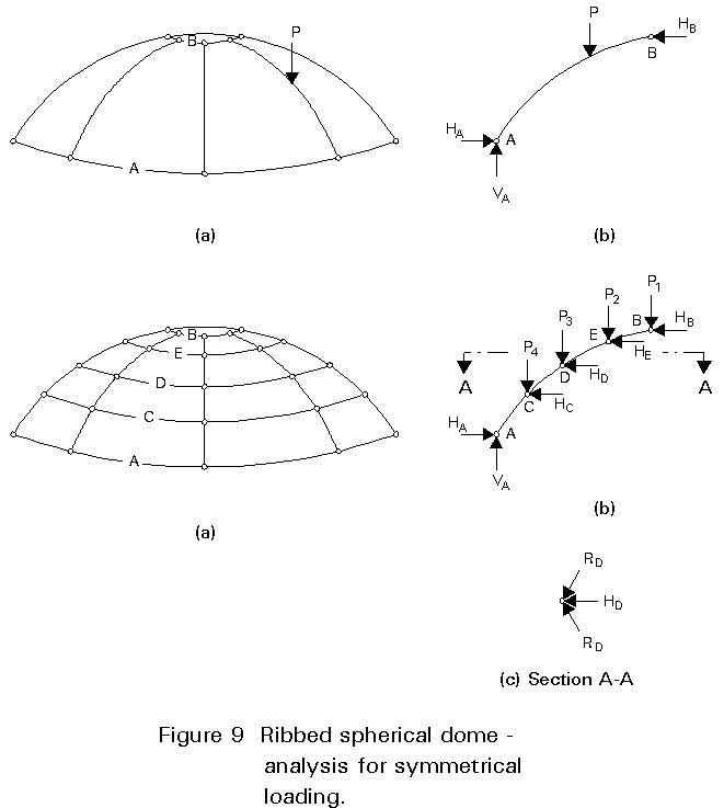
Economy depends primarily upon the rise-to-span ratio of the dome, and the number of ribs and rings to be used. A rise-to-span ratio around 0,13, i.e. when the spherical radius is equal to the dome diameter, provides the maximum structural economy according to some authors.
These structural systems play an interesting role in modern construction and are examined in detail below.
High strength steel cables have been used extensively over the past twenty five years for space roof structures.
There are two different possibilities when using steel cables in roof structures.
The first possibility, consists of using the cables only for suspension of the main roof structure, which can be either conventional, e.g. beams, cantilevers, etc., or a space frame. In this case, the main roof structure, instead of being supported, is actually suspended from steel cables above the roof, which transmit the tensile forces to appropriate anchorages (Figure 10). They are cable-stayed roofs.
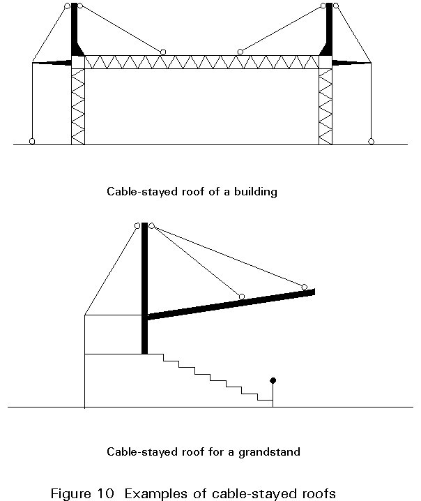
There are many examples of this type of construction used as industrial buildings where the roof structure, either as a single or as a double cantilever, is suspended from cables, which in turn are anchored on robust pylons above the roof level.
In this type of construction, the cables behave as simple suspension elements, while the roof structure itself behaves like a normal load resisting unit, subject to moments, shears, and other kinds of action effect. It is expected that the suspending elements remain in tension, even under wind uplift, due to the dead weight of the roof.
The second possibility is represented by those roof structures where the steel cables are effective members of the roof structure itself, and not just conveyors of forces from the structure to the anchorages. In this type of construction (tension structures), the cables themselves resist the various external loads. Their particular behaviour has deeply influenced the structural forms used and has imposed new methods of execution.
Tension structures may be categorised as:
(a) Single-layer cable systems (Figure 11a)
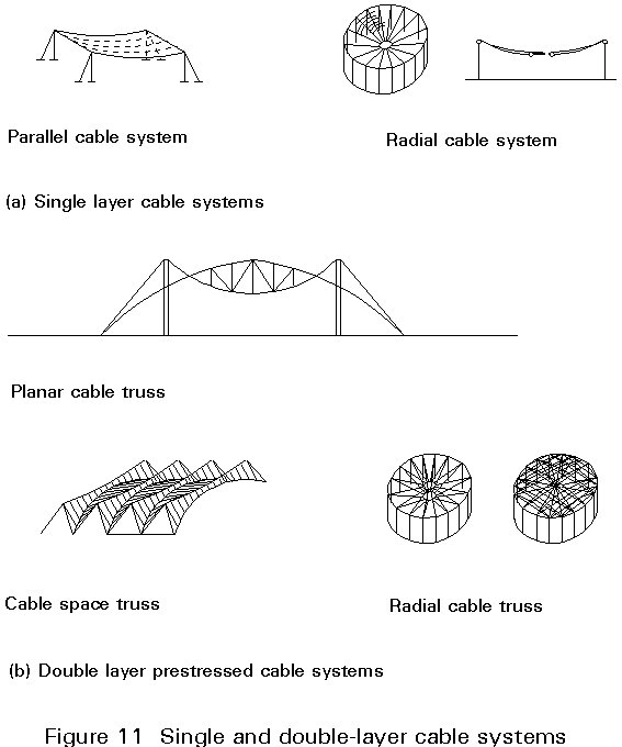
(b) Double-layer prestressed cable truss systems (Figure 11b)
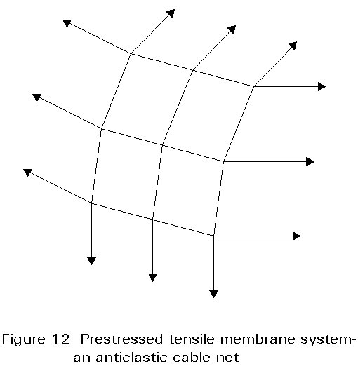
(c) Prestressed tensile membrane systems (Figure 12)
Tension structures are used to cover stadia, arenas, swimming pools, recreation halls and other buildings where a large area for public assembly and exceptional aesthetic effect are required simultaneously.
There are some particular problems associated with these cable-stayed and tension roof structures.
A first problem derives from the fact that the cable is flexible. It assumes a shape compatible with the applied loads whilst architectural and building requirements demand that the structure has a definite form. Any deviations from that form due to the action of the applied loads, must be kept to a minimum. To meet this requirement, a pretension must be introduced into the structure, which must be compatible with the desired shape, and when combined with the applied loads, must maintain the deformation between specified limits. Design may therefore involve use of mathematical 'form-finding' procedures, implemented by appropriate software.
Another feature of these structures is their geometrically non-linear behaviour. Deformations play an essential role in the analysis and the principle of superposition of effects is not valid.
Finally, an important problem associated with these structures is their sensitivity to aerodynamic instability, e.g. flutter. This sensitivity imposes special requirements on the design and the constructional details of these systems, particularly those which use membranes made of lightweight fabric as cladding.
The requirements of stiffness under transverse loading and anchorage are major form determinants for cable structures, and these are examined in the following sections.
Single cable structures are characterised by their flexibility, Figure 13. They require stiffening to prevent a change of shape with each variation in load and to make them capable of resisting uplift due to wind, Figure 14. Gusty winds can produce oscillations, unless damping is provided to the structure.

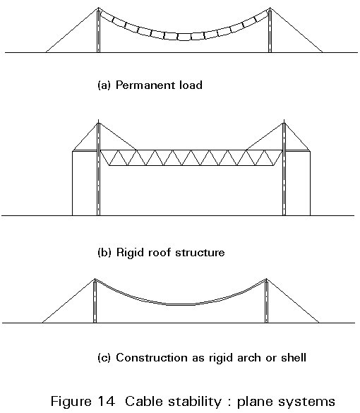
The principal methods of providing stability are the following:
(i) Additional permanent load supported on, or suspended from, the roof, sufficient to neutralise the effects of asymmetrical variable actions or uplift Figure 14a).
This arrangement has the drawback that it eliminates the lightweight nature of the structure, adding significant cost to the entire structure.
(ii) Rigid members acting as beams, where permanent load may not be adequate to counteract uplift forces completely, but where there is sufficient flexural rigidity to deal with the nett uplift forces, whilst availing of cables to help resist effects of gravity loading (Figure 14b).
(iii) Rigid surfaces behaving as inverted shells or vaults, where uplift forces are countered by the in-plane compressive rigidity of the structure (Figure 14c).
(iv) Secondary cables prestressing the main cables so that these remain in tension under all conditions of load. Such prestressing can take a variety of forms:
× a stayed (guyed) arrangement, wherein the main cable is stayed to other elements or to the ground, as in the case of guyed trusses (Figure 14d).
× A planar arrangement of suspension and stabilising cables, with opposite curvatures cables, Figure 14e. This structure reacts elastically to all changes of shape provoked by the externally applied loads. This principle can be extended to permit creation of space trusses, or structures of revolution.
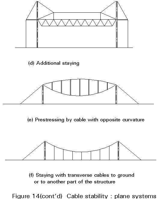
× An orthogonal or diagonal arrangement of suspension and stabilising cables, with opposite curvatures, forming an anticlastic (saddle-shaped) surface, Figure 14f and 15.
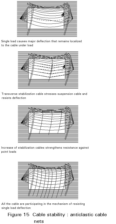
Figures 14 and 15 show the application of these general principles to cable and cable-stayed systems, whilst Figure 16 details the structural actions of prestressed cable truss systems. Accurately defined, a cable truss system has a triangulated structural form which increases stiffness, particularly under non-symmetric loading. However, the term is also frequently applied to the cables with opposite curvature shown in Figure 14e.
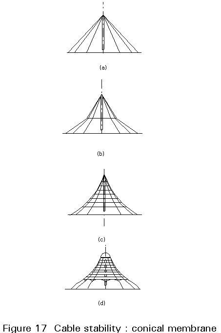
The orthogonal or diagonal arrangement of anticlastic cables shown in Figure 15 can also be extended to the conical form shown in Figure 17. The increasing use of horizontal ring cables, from Figure 17a to 17c enhances stiffness against asymmetric loading. Because of the difficulty of anchoring a large number of cables at a point, the top is usually flattened as shown in Figure 17d.
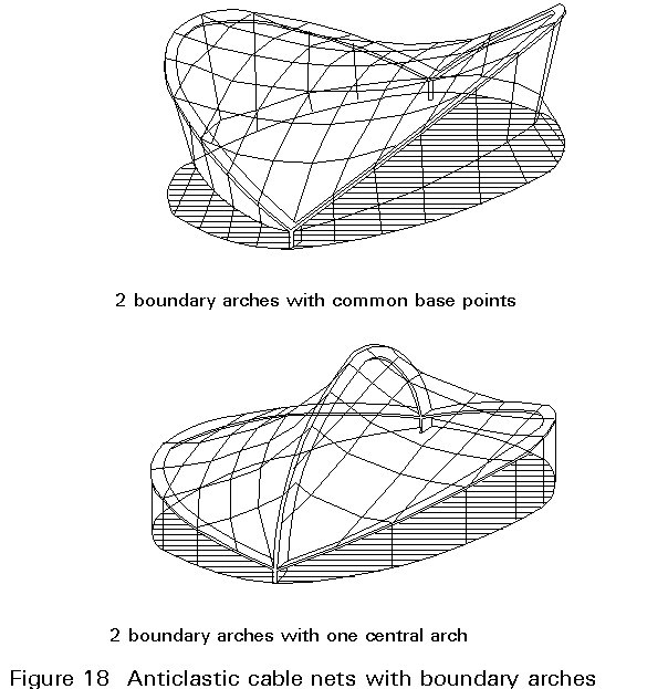
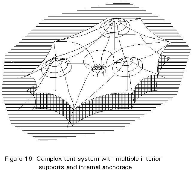
The use of anticlastic cable nets is further enhanced by the use of internal arches, Figure 18. The use of conical forms can be extended to create exciting doubly curved surfaces by the use of multiple high points and/or interior anchorages, Figure 19. The Pavilion of the Federal Republic of Germany, Expo 1967, Montreal by Frei Alto and Rolf Gutbred was an outstanding example of the former.
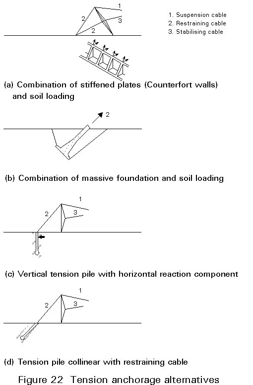
Cable stayed structures generate a requirement for the anchoring of tension forces. Some of the commoner solutions are:
(i) Vertical and horizontal reactions provided by axially loaded elements - stayed columns used with ground anchors (Figure 20a).
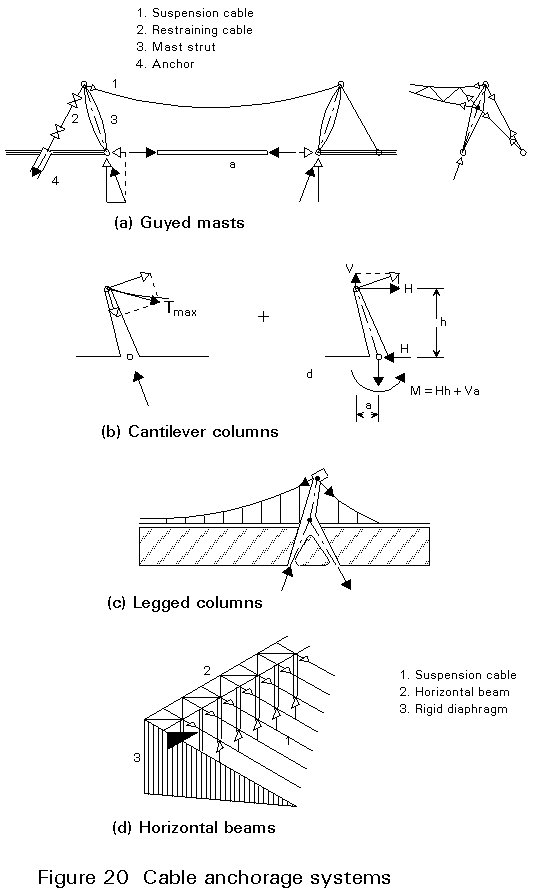
(ii) Vertical and horizontal reactions provided by flexural elements i.e. cantilever columns (Figure 20b) or legged columns (Figure 20c).
(iii) Vertical columns acting with horizontally loaded edge beams which transfer horizontal reactions to rigid diaphragms (Figure 20d).
(iv) Inclined walls, or vertical cylindrically curved walls (Figure 21a).
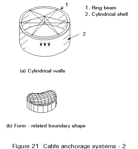
(v) Form-related boundary shapes, creating, in some cases, a closed self-equilibrating system of tension and compressive forces and requiring no tension ground anchors (Figure 21b).
The magnitude of forces in stayed columns and in diagonal stay restraining cables is reduced by inclining the columns. In some symmetrical structures lateral thrust is balanced by means of struts at foundation level.
Some tension anchorage possibilities are illustrated in Figure 22.
Cantilever construction is used extensively for large hangars, the column free interior and facade permitting the required ease of access and flexibility of use. Sliding doors around the perimeter are vertically supported on rollers at ground level and laterally supported by the roof structure. The deflection of the cantilever roof structure must be allowed for on the design of the doors.
Single or double cantilever systems may be used. In the single cantilever system, substantial foundations must be provided to counteract the overturning moment. With symmetrical double cantilever systems, the permanent loads on either side of the central block balance each other. The central block which frequently contains offices and circulation areas, may be used to counteract the effects of unsymmetrical loading.
In regard to the composition of the cantilever, roof structures may be categorised as follows:
(a) Pure cantilever systems, formed of varying-depth trusses, girders, folded plates and shells (Figure 23a).
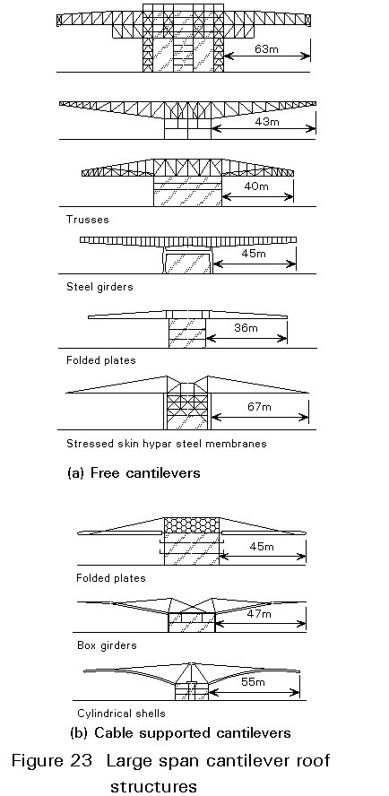
(b) Cable supported structures, supporting any of the above structures types (Figure 23b).
In addition to gravity loading and temperature effects, the roof structure is exposed to wind loading on its upper and lower surfaces. In the case of cable-stayed structures, particular attention must be paid to uplift.