ESDEP WG 1B
STEEL CONSTRUCTION:
INTRODUCTION TO DESIGN
To report the lessons from past failures which may improve the safety of future design and methods of execution.
None
None.
In this lecture nine failures are examined. The analysis of these particular cases allows identification of the lack of knowledge or the type of error for the structures concerned. From the analyses, the lessons for future design and execution are highlighted.
Examples of failures due to seismic action are not dealt with, see the lectures of Group 17.
In pre-industrial societies, technology and architecture were based largely on a craft approach. The design of objects and buildings changed very slowly over time as gradual improvements were made.
Concepts of progress are not therefore a new idea, but in medieval society builders were restrained to build very carefully, both figuratively and literally, on what had been done before. Failures occurred when they tried to go too far beyond the "state of the art" reached through centuries of slow development.
Cases of failure can be found in the most important and most visible constructions built at that time, the cathedrals. In their desire to have the tallest nave or the widest span in Christendom, the cathedral authorities and builders sometimes strayed beyond the limits of their knowledge and technology. As a result some buildings or parts of buildings collapsed. This was the case with the cathedral of Beauvais. The collapse occurred because the builders had overreached themselves and taken the Gothic structural system beyond its natural limits.
The growth of interest in scientific method and reasoning which started in the seventeenth century led to the industrial revolution. It included development of the ability to predict in advance the forces to which a structure might be subjected when in use. The same process of industrialisation also allowed the production of new materials whose properties were more regular and predictable than those of the natural materials which they replaced. The combined increase in knowledge and improvement in materials might have been expected to have caused a reduction in the occurrence of structural failures. However, the growth of industrialisation produced a demand for many types of structure for which there was no historical precedent, such as railway stations, covered markets, and exhibition halls.
With the progress of technology came an expectation of novelty from the public and a desire to create it on the part of designers; suddenly it seemed as if almost anything was possible as development accelerated. Each successive structure was for a time the longest, tallest, or had the greatest span. The nineteenth century was a time when designers were faced continuously with trying to solve problems for which there was no precedent.
Without changing demands from society and progress in technology, failures would be caused only by carelessness. By the study of failures, it is possible to learn how to make structures safer as technology develops. This is the subject of the present lecture.
Failure is by no means the prerogative of ignorance or incompetence. It is more often the consequence of a rare lapse, which team work and vigilance have for once failed to remedy. This lapse may be compounded by ill-luck, by inadequate communication, by safety margins too small to allow for human fallibility, by inexact methods of calculation or construction, etc.
It would be foolish to attempt in a single lecture to make a complete list of reasons for failure and to try to present examples of each. However there are two recurrent themes, most failures occur during erection and one of the most important reasons for structures failing is lack of communication. Poor communication may manifest itself in many different ways. The best guard against it is for all the engineers involved in a job to know each other, to regard each other as friends as well as colleagues involved in a joint enterprise, and most of all to maintain sympathy for one another's views. The difficulty of achieving and maintaining these relationships in a complex contractual situation is discussed in the following section.
Only a very few of the many other reasons for failures recur sufficiently often to warrant specific discussion. Poor detailing may be caused by lack of understanding or by omissions in checking. Numerical error in calculation rarely leads to failure. The inclination to minimise material use, or maximise stresses may also be carried too far, producing only small gain in terms of cost, greater cost in terms of the required accuracy of analysis and/or increased risk of failure. One very clear danger lies in using designs which have proved successful at one scale as a basis for larger structures. The main problem here lies in omissions which were unimportant at the smaller scale becoming significant at the larger scale.
Usually a job starts with a client who employs an architect to design the structure and control all the other input. The latter will ask a consultant to design the structure. Frequently the consultant produces an outline and member sizes but no joint details. Tender documents will be sent out for the complete structure and each main contractor will ask for subcontract prices for many items of work. Usually the steel frame would be one of these items. In bridgework the architect would not control the work but the main contract/subcontract relationship would still exist.
Once the contracts are let, the steelwork subcontractor will design the connections and begin fabrication. Sometimes even this task is subdivided, with the steelwork subcontractor on the main contract subletting the fabrication work and only doing the erection himself. All of the people mentioned, including "The Engineer"*, who may or may not be the consultant/designer, are bound in a contractual relationship with one another. The contract is very important but is sometimes allowed to disrupt personal relationships between individuals. If ever a breakdown in the friendships between professionals can be seen in a job, then it may be regarded as a clear indication of danger. It is not possible for everyone to carry out their job effectively if there is animosity at any level.
To complicate the problem further, the work is carried out by a labour force which has a corporate identity but which is also a gathering of skilled groups made up of individuals. Safe and economical completion of a job depends on all the members of the team. Mutual respect of skills and interests is needed. If that is maintained, the chances of failure are reduced to negligible proportions. The courage to question the work of others must be matched by a willingness to accept questions and help from others. Similarly the courage to resist pressure for undesirable change is always necessary.
Four failures of steel box girder bridges of somewhat similar design took place during construction in different parts of the world during the years 1969-1971. It is remarkable that no two of these failures were really alike. Two of the bridges were in the cantilever condition when collapse occurred, one of these failed as a result of bottom flange weakness, the other by collapse of a load-bearing diaphragm. One of the other two failed as a result of top flange weakness. The other buckled at the bottom due to temperature differential. All four failures were, however, associated with instability of thin plates in compression.
The main causes of these accidents were:
a. the application of buckling theory with inadequate factors of safety;
b. poor detailing rules and the absence of adequate fabrication tolerances.
The bridges that failed were, in chronological order:
A brief description of two of these failures is given below:
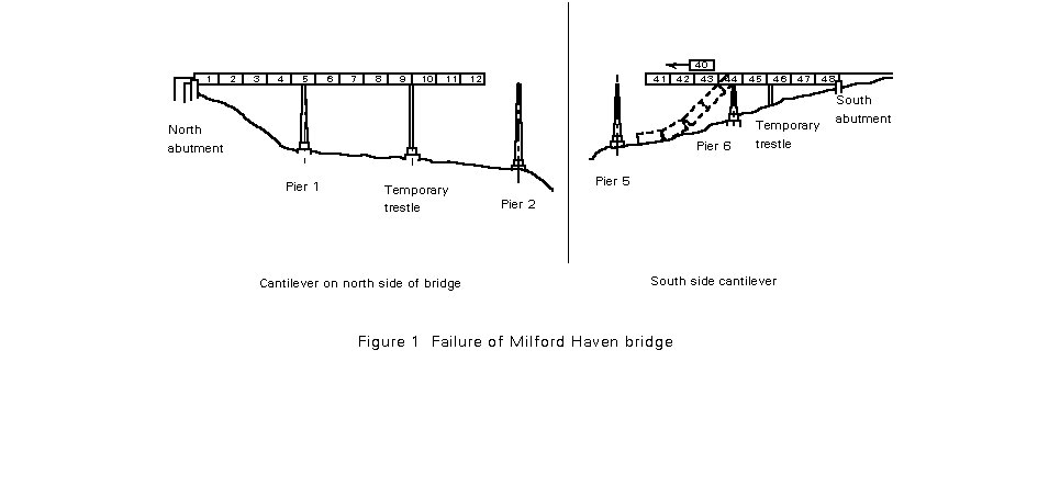
Milford Haven Bridge
A local failure during erection of the cantilever on the south side of the bridge led to global collapse. The member concerned was a load bearing diaphragm.
The bridge (Figure 1) was originally designed as a single continuous box girder of welded steel. (It was rebuilt as a cantilever and suspended span in the main span). The spans measured from the south 77m, 77m, 77m, 149m, 213m, 149m and 77m. The span that collapsed was the second 77m span on the south side, the first having been erected with the aid of a temporary support. The collapse occurred when the last section of box for the second span was being moved out along the cantilever. When the collapse occurred this section slid forward down the cantilever killing four men.
It is clear from the reports of the failure that it was initiated by buckling of the support diaphragm at the root of the cantilever being erected (Figure 2). The diaphragm was torn away from the sloping webs near the bottom of the box, allowing buckling of the lower web and bottom flange to take place. As the diaphragm buckled, it shortened, reducing the overall depth of the box girder; the tendency of the bottom flange to buckle was inevitably increased by this reduction of the distance between flanges which increased the force needed in each flange to carry the moment with a reduced lever arm.
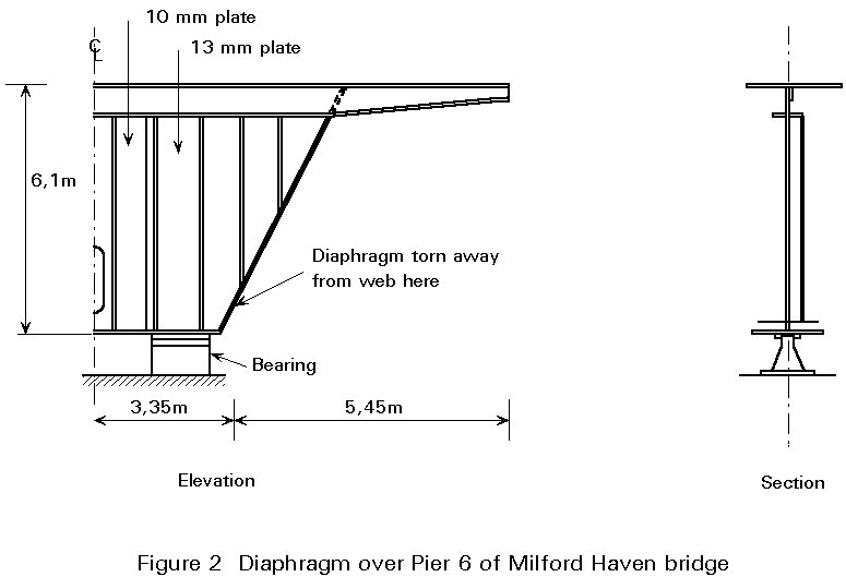
The support diaphragm was in fact a transverse plate girder, which carried heavy loads from the webs at its extreme ends, and was supported by the bearings as shown in Figure 2, some distance from its ends. It was therefore subjected to a hogging bending moment and a large vertical shear force. The diaphragm plate near the outer bottom corners was subject to a complex combination of actions. The shear of the transverse girder and diffusion of the point load from the bearings was compounded with the effects of inclination of the webs of the main bridge girder which produced an additional horizontal compression action, and out-of-plane bending effects caused by bearing eccentricity.
The load sustained by the diaphragm just before failure was reported to be nearly 9700kN, which agrees tolerably well with independent calculations of strength made after the accident. The calculated design resistance, using design rules that were drafted subsequently and making allowance for likely values of distortion and residual stresses would be considerably less, possibly as low as 5000kN.
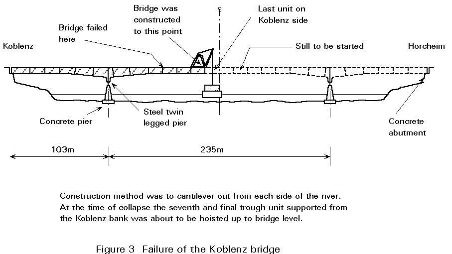
Rhine Bridge, Koblenz
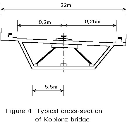
The centre span of the Koblenz bridge over the Rhine collapsed during construction on 10 November 1971, when erection had almost reached the mid-point of the 235m span (Figure 3). The bridge was a single steel box, 16,4m wide at the top plus cantilevers, and 11m wide at the bottom (Figure 4). The box was erected by cantilevering, 85 tons being lifted at a time.
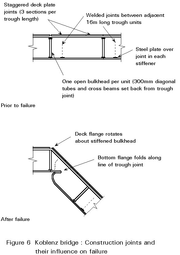
The bottom flange was stiffened longitudinally by T-stiffeners, and the box was stiffened transversely by frames with diagonals made of 300mm diameter steel tubes. All site joints were welded, a comparatively new technique in Germany at the time. As shown in Figure 5, a 460mm gap was provided in the longitudinal T-stiffeners of the lower flange to permit the passage of automatic welding equipment making the transverse butt weld splicing the flange plate. The T-stiffener was then itself spliced by welding in two plates, the plate splicing the web of the T being just 460mm long and butt welded. To avoid a local concentration of residual welding stresses, this plate was not welded to the bottom flange of the box, but was set with its bottom edge 30mm clear of the flange. The plate splicing the table of the T was lapped on top of the ends of the two Ts.
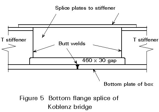
Thus it will be seen that:
Subsequent investigation showed that the bottom flange plate could carry its stress safely if out-of-straightness was no more than 0,95mm on the 460mm unsupported length. In fact the plate was out-of-straight by as much as 2mm at some points.
On the afternoon of 10 November 1971, preparations to lift the last section of the cantilever from the Koblenz side were complete. Lifting cables were tightened, thus taking part of the weight. A metallic click was heard. The tip of the cantilever settled slightly. A few seconds later the bottom flange splice 50m from the pier buckled and the nose of the cantilever collapsed into the water. The click was undoubtedly the sudden folding up of the flange plate at the splice into the 30mm recess. Much of the stress that should have been carried by the plate was consequently thrown off onto the T stiffeners. They were then taking three times their proper stress, and they buckled too (Figure 6). Thirteen men were killed.
The inquiry concluded that there had been no negligence. The design calculations had all been done correctly according to the methods then normally used in Germany. Rather it was the case that the methods needed revision.
King's Bridge in Melbourne
The collapse of the King's bridge in Melbourne is one of the relatively few examples of failure in service. The bridge was opened in 1961 but only 15 months later, on 10 July 1962 (Melbourne's winter), it failed by brittle fracture when a 45 ton vehicle was passing over it. Total collapse was prevented by walls which had been built to enclose the space under the affected span. Investigation showed that many other spans of the bridge were in danger of similar failure.
The foundations were in good order. The superstructure consisted of many spans in which each carriageway was supported by four steel plate girders spanning 30m, topped with a reinforced concrete deck slab. Figure 7 shows a typical girder. The bottom flange of each plate girder consisted of a 400mm x 20mm plate, supplemented in the region of high bending moment by an additional cover plate which was either 300 x 20mm or 360 x 12mm. The cover plate was attached to the flange by a continuous 5mm fillet weld all round.
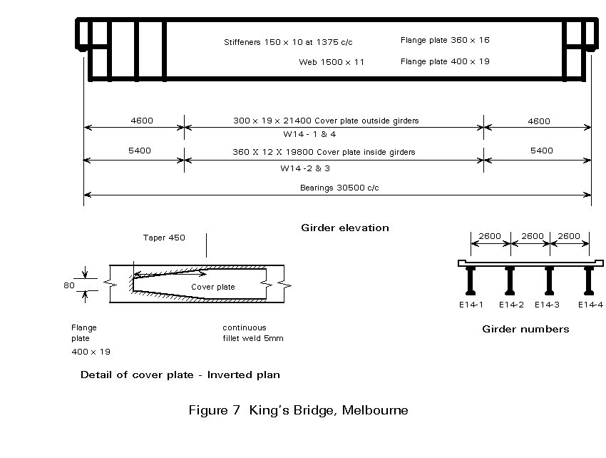
The steel specified was to comply with BS968: 1941, an earlier version of BS4360 Grade 50 or Fe E 355. BS968 at that time contained no requirement for low temperature notch ductility, but the specification writer for the bridge did add some special requirements of this type. Despite these additional clauses, those who built and inspected the bridge did not understand that high strength steel needed special care in welding when compared with mild steel (grade 43 or Fe E 275 as it is now called). Difficulties were experienced with welding but an expert was not called in at the time.
Subsequent inspection showed that cracks existed in the main flange plate under 7 of the 8 transverse fillet welds in the span which failed. One crack had extended partly by brittle fracture and partly by fatigue until the tension flange was completely severed, and it had extended half way up the web. All 7 cracks developed into complete flange failures when the failure occurred under a load that was well within the design load. In some instances the entire girder was severed and there was no loss of life. Total collapse was averted by the supporting walls.
Thus the failure of King's Bridge was due to a poor detail which would not be reproduced now, compounded by poor communication which led to a lack of necessary inspection.
Quinnipiac River Bridge
A less dramatic accident occurred in 1973 on the Quinnipiac river bridge near New Haven (USA). A large crack was discovered in a fascia girder of a suspended span.
The structure is non-composite and the girders are 2,8m deep at the crack location. The structure had been in service for approximately 9 years at the time the crack was discovered.
The crack was situated approximately 10m from the west end of the suspended span which is 50m long.
Figure 8 shows the crack that developed in the girder web. The crack propagated to the mid-depth of the girder and had penetrated the bottom flange surface when discovered.
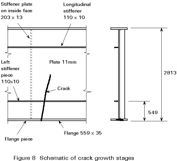
Examination of the fracture surface indicated that crack growth had occurred in a number of stages and modes. These stages are shown schematically in Figure 9.
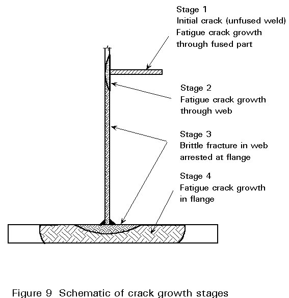
During fabrication a crude partial penetration weld was placed across the width of the longitudinal stiffener. It is probable that some crack extension from the unfused section occurred during transport, erection and early service. Assuming normal random traffic and approximately 6mm of the 9,5mm thick longitudinal stiffener were unfused, fatigue cracking would require between 2 000 000 cycles and 20 000 000 cycles (depending on the proximity to a free surface) to propagate through the longitudinal stiffener thickness. If the crack had only been fused about 3,8mm on one plate surface so that an edge crack resulted, only about 1 000 000 cycles of random traffic would be needed to propagate the crack through the longitudinal stiffener. Fatigue crack growth (Stage II) would develop mainly after the stiffener was cracked in two. Electron microscope studies of the fracture surface confirmed the presence of fatigue crack growth striations during stage 2.
Stage 3 was the brittle fracture of the web during a time of low temperature. It was initiated in a zone of high residual tensile stresses. Once the crack became unstable, it propagated through the zone of lower stresses in the web and was eventually arrested in the flange. Further fatigue crack growth (Stage 4) developed thereafter and continued until the crack was discovered and repaired.
In this case the failure was due to a weld containing an internal defect (lack of fusion) which initiated a fatigue crack. Total failure was avoided by the detection of the crack during regular inspection.
Bridge on the Sainte Marguerite River in Sept-Iles (Quebec)
As in the Milford Haven bridge a local failure led to global collapse. The bridge on the Sainte Marguerite River consisted of five steel plate girders made composite with the deck. As shown in Figures 10 and 11, each girder had four supports, two on the abutments and two on cross-beams joining the top of the inclined legs at an angle of 45° strut.
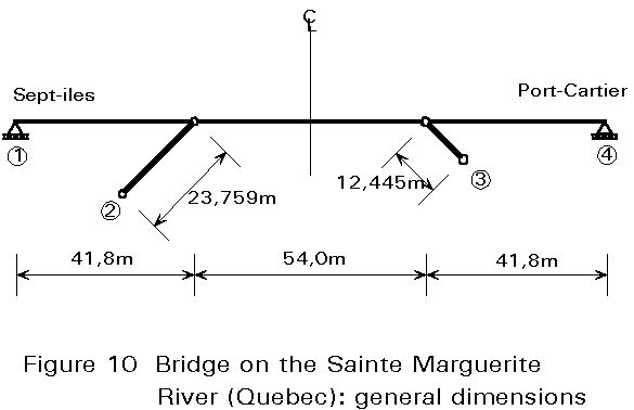
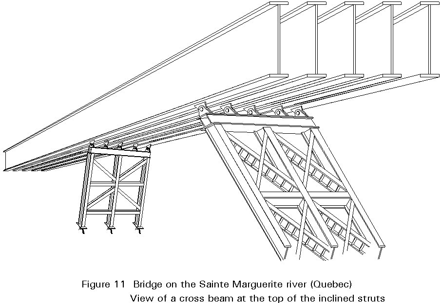
The cross-beams were supported by a group of three braced struts at the same inclination. The bridge deck consisted of a concrete slab (220mm) with an asphalt layer of 65mm. The composite behaviour was provided by stud connectors welded on the steel girders.
The bridge failed during the asphalt surfacing. The failure was initiated by a local buckling of the webs of the struts on the Sept-Iles side (Figure 12). The support provided by these struts vanished and, as a result, the span increased from 54,0m to 95,8m. The bending moment in the main girders was multiplied by a factor of 5. The composite girders and deck were not able to resist and failed.
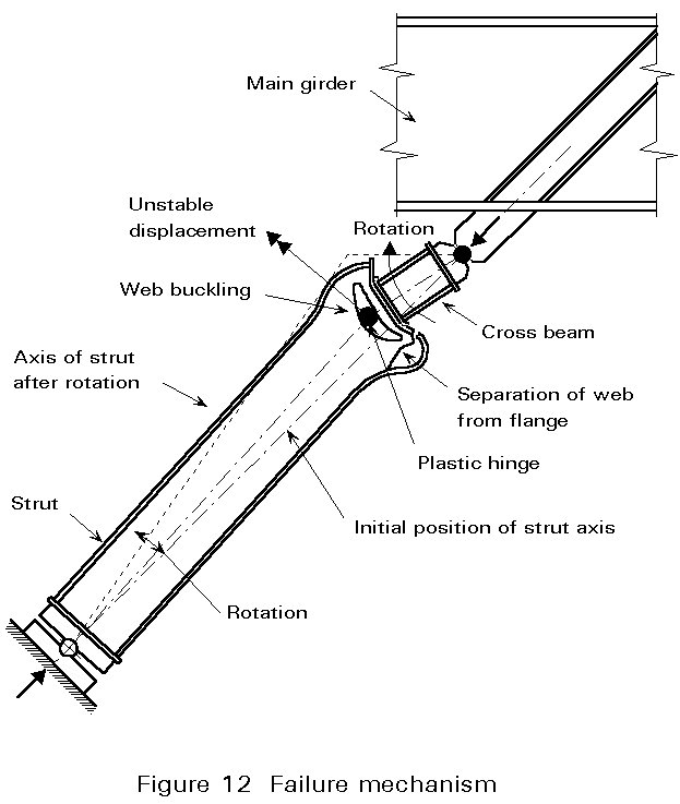
The main reason for the failure was found in the assembly between cross-beam and struts. Without stiffeners the webs of the struts (WWF 900 x 293) were too slender and not able to resist the axial loads transmitted by the cross-beam. The width to thickness ratio of the webs had a value of 76,7 while the limiting value is about 34 for the steel considered (following Eurocode 3: b/t £ 42 e and e = ![]() ). In this condition, the maximum axial load which could be carried by the strut was about 3300 kN, a value later confirmed by test. The strut load at the moment of failure had a value of 3500kN while the calculated service load was 5780kN.
). In this condition, the maximum axial load which could be carried by the strut was about 3300 kN, a value later confirmed by test. The strut load at the moment of failure had a value of 3500kN while the calculated service load was 5780kN.
To carry the service loads with a reasonable safety factor it was necessary to place stiffeners on the web of each strut in order to obtain full collaboration of the web (Figure 13).
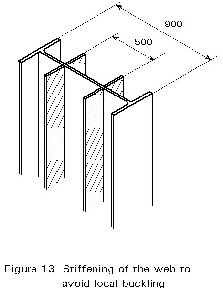
This failure can be attributed to an insufficient knowledge of the behaviour in compression of struts with slender webs.
The Seneffe Water Tower (Belgium)
A type of steel water tower which is rather popular in Belgium and abroad, is shown in Figure 14a. The main shell, where the water is stored, is theoretically axisymmetrical about the vertical axis and is often compared to a golf ball with its Tee support. Such a water tower with a capacity of 1500 cubic metres was built in 1972 near the industrial park of Seneffe; the main dimensions are shown in Figures 14a. and b. Two conical shells made of 8 and 15mm thickness steel formed the main part of the water tower.
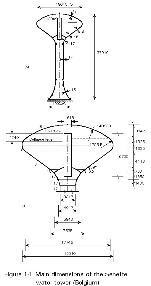
The initial design was made using membrane theory. Assessment of local bending stresses at the shell intersection was derived from an axisymmetrical analysis using finite elements. Both computation methods were of the first order but they did not take account of any instability phenomena. Indeed, due to internal pressure, the hoop stresses in the part AB of the water tower (which were found later to be critical) are tensile; in spite of the fact that the meridional stresses in the upper part are compressive, no analysis of a possible buckling of the conical shells was undertaken.
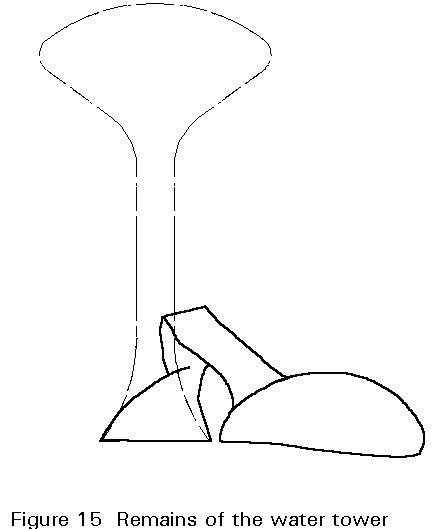
During the first filling test the water tower collapsed when the water level corresponded to a volume of 1130 cubic metres, i.e. when the water had risen to 1,74m below the overflow level (Figure 14). Failure occurred by buckling on the thin cone near the junction of the two cones. The collapsed structure is shown in Figure 15.
After the accident the available literature was carefully scrutinized and the following conclusions emerged:
a. Imperfections, which may be geometrical or structural. The welding procedure, used quite generally to assemble the various components of a branched shell such as that shown in Figure 14, produced both local geometric imperfections and high residual stresses. The residual stresses are never reduced by an annealing treatment except in steel nuclear vessels.
b. Discontinuity stresses, which have high local peaks at the intersections of branched shells.
At that time, even using the most advanced information on stability of isolated shells, it was only possible to have an idea of the collapse resistance of a very perfect shell under idealised boundary conditions. The available literature disregarded entirely the effect of imperfections and discontinuity stresses.
The failure of the Seneffe water tower was the starting point for important experimental research in the fields of liquid-filled conical shells and of nonlinear computer analysis taking into account geometrical imperfections.
The last edition (1988) of the ECCS Recommendations on the Buckling of Steel Shells gives much information for a wide range of cylindrical, conical and spherical shells. Current design recommendations relating to the buckling of manufactured shell structures now take account of realistic levels of geometric imperfections and residual stresses.
Wind effects on a steel chimney
After a five-year service period a 25,81m high steel chimney in a group of four chimneys partially failed during a storm with windspeeds of between 120 and 150km/h.
The four chimneys consisted of conical and cylindrical shells of 800mm diameter assembled by bolted flanges or by welding (Figure 16). In the bolted connection of an external flange located at a height above ground of 13,575m, 13 of the 24 bolts broke. The deformation of the flange led to a perceptible slope of the upper part of the chimney, which did not fall.

At the moment of the accident the wind blew along the line of the four chimneys, from West to East. The fourth chimney (down wind) was damaged and the failure of the bolts affected the South part of the flange. This position corresponded to bending of the chimney perpendicular to the wind direction which is a characteristic of vortex shedding.
Where cylinders are in line, the effects of vortex shedding are greater on and after the second cylinder than on an isolated cylinder when the distance from axis to axis is less than 10 diameters. The effects can be doubled.
The forces on the bolts due to the bending perpendicular to the wind direction were unfortunately underestimated and the flanges were not stiff enough. The failure of the bolts was due to fatigue in bending and was initiated in an overloaded bolt. The overloading was due to inadequate tightening of adjoining bolts and to deformation of the flange.
The main reason for the failure was because the amplification of vortex shedding in the case of chimneys in line was not taken into account. In Eurocode 1: Basis of Design and Actions on Structures, special attention will be given to the additional dynamic effects of wind on structures.
Zoology Block, Aberdeen University
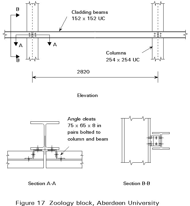
The Zoology Block was a rectangular six-storey building with a steel frame and a plan area of 13 metres x 65 metres. The steel columns were placed along both sides of the building at 2,82 metre centres and carried steel beams 686mm deep which spanned the full 13 metres. Figure 17 shows the simple angle brackets that were fixed to the external face of the columns and supported horizontal 152mm x 152mm steel universal column sections; these were to carry the proposed cladding of precast concrete panels. The floors were precast concrete planks bearing directly onto the 13 metre span main beams.
After erecting the steelwork, the contractor decided to install the floors to facilitate later work. Unfortunately, with the additional weight of the precast concrete planks, the columns of the building were on the point of buckling in the long direction of the building and a light wind provided the necessary disturbing force. The whole building collapsed in the longitudinal direction with the floors stacked one above the other. Four men were found dead in the wreckage and one died later. Several others were injured.
The wind was not unusually strong on the day of the collapse, but it was enough to put the building out of plumb. Once the structure moved out of the vertical, the mass of the concrete floors created a large overturning moment. The only stiffness in the plane of the collapse was in the cleats which attached the cladding rails to the frames formed by the main columns and beams. The cladding rails passed outside the plane of the columns and the fixing cleats were virtually pin joints and allowed the rails to rotate relative to the columns.
The main reason for the collapse was the lack of sway restraint, which would have been provided once the cladding panels were in place to stiffen the structure. It could be concluded therefore that the mistake lay in the process of erection; the cladding should have gone in before the floor panels. However the contractor had no reason to assume that the steel frame could not support all the possible loads applied to the building. He should have been told if this was the case. This would mean that the mistake was one of communication. If the connections between the cladding supports and the columns had been designed to be somewhat stiffer, the collapse would have been unlikely to have happened. Tests and calculations made subsequently showed that collapse of the building in the long direction was much more likely than collapse in the short direction, although it is the latter, with the longer face exposed to the wind load, that would generally be thought more likely. Under the steelwork design code, Eurocode 3, the contractor should be informed if the steel frame is not stable in its own right before the cladding is put on it, so that he can then plan the erection sequence accordingly.
During the investigation into the collapse, it was discovered that the original cleat detail for the cladding rails, which would have provided some stiffness in the plane of the collapse, had been revised when erecting the frame because the cleats were "awkward" to construct on site. In the end both the designers of the steel frame and the contractor who erected it were found liable for the collapse because of their "most unfortunate and quite unintentional misunderstanding" due to lack of communication.
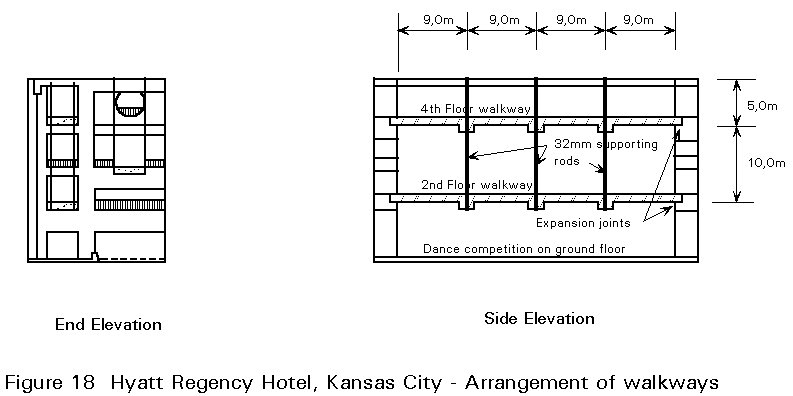
Hyatt Regency Hotel, Kansas City
On the 7 July 1981, a dance was being held in the lobby of the Hyatt Regency Hotel, Kansas City. As spectators gathered on suspended high level walkways, the supports gave way and two levels of bridge fell to the crowded dance floor. One hundred and eleven people died and nearly two hundred were seriously injured. Failure occurred at a simple but critical detail.
The walkways crossed the lobby at second and fourth floor levels and were supported above one another by hanger rods from the fifth floor (Figure 18). Floor to floor height was 5m and the walkways hung from three sets of hangers at 9m centres. In the original design single 15m long rods supported the two walkways (Figure 19(a)). At each level a cross-beam made from two channels welded toe to toe rested on a nut and washer on the rod. This detail would not have failed under the loading imposed even though its strength was only one quarter of that required by local design codes.
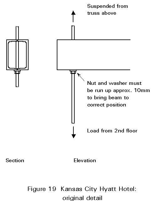
In the furore which followed the collapse it became obvious that the design had been changed to reduce the cost of the connection. The second floor walkway was actually suspended from the fourth floor one (Figure 19(b)). As a result the connection between the fourth floor cross-beam and the hanger supported double the load originally intended, or rather failed to do so. The alteration seems to have been recommended by an engineer, not party to the original design, who specialised in reducing costs. Unfortunately he failed to understand the importance of the details changed: nor was the effect of the changes spotted by any of the other parties involved.
Once again, a gross underdesign of a detail would not have caused failure had not another factor resulted in a significantly increased load. Here, as in most failures, lack of communication was the most important reason why failure was not prevented.
× poor communication.
× design error or lack of understanding of structural behaviour.
× a material-related problem causing failure in a structure even though its behaviour is reasonably well understood by the designer.
× errors in detailing or poor detailing rules caused by lack of understanding or checking.
× inadequate temporary works, lack of thought about a temporary condition or about the process of erection.