ESDEP WG 2
APPLIED METALLURGY
The lecture briefly discusses the basics of the welding process and then examines the factors governing the weldability of structural steels.
None.
Lectures 2.3: Engineering Properties of Steels
Lecture 2.4: Steel Grades and Qualities
Lecture 2.5: Selection of Steel Quality
Lecture 3.3: Principles of Welding
Lecture 3.4: Welding Processes
Lectures 11.2: Welded Connections
The fundamental aspects of the welding process are discussed. The lecture then focuses on the metallurgical parameters affecting the weldability of structural steels. A steel is considered to exhibit good weldability if joints in the steel possess adequate strength and toughness in service.
Solidification cracking, heat affected zone - liquation cracking, hydrogen-induced cracking, lamellar tearing, and re-heat cracking are described. These effects are detrimental to the performance of welded joints. Measures required to avoid them are examined.
Welding is a joining process in which joint production can be achieved with the use of high temperatures, high pressures or both. In this lecture, only the use of high temperatures to produce a joint is discussed since this is, by far, the most common method of welding structural steels. It is essentially a process in which an intense heat source is applied to the surfaces to be joined to achieve local melting. It is common for further "filler metal" to be added to the molten weld pool to bridge the gap between the surfaces and to produce the required weld shape and dimensions on cooling. The most common welding processes for structural steelwork use an electric arc maintained between the filler metal rod and the workpiece to provide the intense heat source.
If unprotected, the molten metal in the weld pool can readily absorb oxygen and nitrogen from the atmosphere. This absorption would lead to porosity and brittleness in the solidified weld metal. The techniques used to avoid gas absorption in the weld pool vary according to the welding process. The main welding processes used to join structural steels are considered in more detail below.
a. Manual Metal Arc welding (MMA)
In this process, the welder uses a metal stick electrode with a fusible mineral coating, in a holder connected to an electrical supply. An arc is struck between the electrode and the weld area which completes the return circuit to the electricity supply. The arc melts both the electrode and the surface region of the workpiece. Electromagnetic forces created in the arc help to throw drops of the molten electrode onto the molten area of the workpiece where the two metals fuse to form the weld pool.
The electrode coating of flux contributes to the content of the weld pool by direct addition of metal and by metallurgical reactions which refine the molten metal. The flux also provides a local gaseous atmosphere which prevents absorption of atmospheric gases by the weld metal.
There are many types of electrodes. The main differences between them are in the flux coating. The three main classes of electrode are shown below:
1. Rutile: General purpose electrodes for applications which do not require strict control of mechanical properties. These electrodes contain a high proportion of titanium oxide in the flux coating.
2. Basic: These electrodes produce welds with better strength and notch toughness than rutile. The electrodes have a coating which contains calcium carbonate and other carbonates and fluorspar.
3. Cellulosic: The arc produced by this type of electrode is very penetrating. These electrodes have a high proportion of combustible organic materials in their coating.
b. Submerged Arc Welding (SAW)
This process uses a bare wire electrode and a flux added separately as granules or powder over the arc and weld pool. The flux protects the molten metal by forming a layer of slag and it also stabilises the arc.
The process is used mainly in a mechanical system feeding a continuous length of wire from a coil whilst the welding lead is moved along the joint. A SAW machine may feed several wires, one behind the other, so that a multi-run weld can be made. Submerged arc welding produces more consistent joints than manual welding, but it is not suitable for areas of difficult access.
c. Gas shielded welding
In this process, a bare wire electrode is used and a shielding gas is fed around the arc and weld pool. This gas prevents contamination of the electrode and weld pool by air. There are three main variations of this process as shown below:
1. MIG (metal-inert gas) welding - Argon or helium gas is used for shielding. This process is generally used for non-ferrous metals.
2. MAG (metal-active gas) welding - Carbon dioxide (usually mixed with argon) is used for shielding. This process is generally used for carbon and carbon-manganese steels.
3. TIG (tungsten-inert gas) - Argon or helium gas is used for shielding and the arc struck between the workpiece and a non-consumable tungsten electrode. This process is generally used for thin sheet work and precision welding.
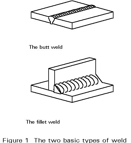
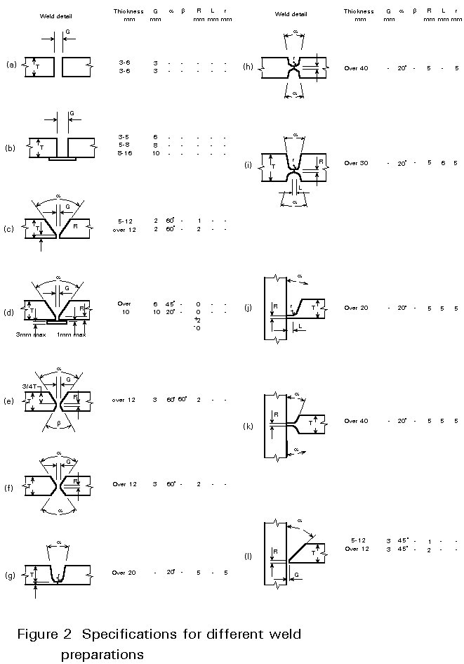
There are two basic types of welded joints known as butt and fillet welds [1]. Schematic views of these two weld types are shown in Figure 1. The actual shape of a weld is determined by the preparation of the area to be joined. The type of weld preparation depends on the welding process and the fabrication procedure. Examples of different weld preparations are shown in Figure 2. The weld joint has to be located and shaped in such a way that it is easily accessible in terms of both the welding process and welding position. The detailed weld shape is designed to distribute the available heat adequately and to assist the control of weld metal penetration and thus to produce a sound joint. Operator induced defects such as lack of penetration and lack of fusion can be difficult to avoid if the joint preparation and design prevent good access for welding.
The intense heat involved in the welding process influences the microstructure of both the weld metal and the parent metal close to the fusion boundary (the boundary between solid and liquid metal). As such, the welding cycle influences the mechanical properties of the joint.
The molten weld pool is rapidly cooled since the metals being joined act as an efficient heat sink. This cooling results in the weld metal having a chill cast microstructure. In the welding of structural steels, the weld filler metal does not usually have the same composition as the parent metal. If the compositions were the same, the rapid cooling could result in hard and brittle phases, e.g. martensite, in the weld metal microstructure. This problem is avoided by using weld filler metals with a lower carbon content than the parent steel.
The parent metal close to the molten weld pool is heated rapidly to a temperature which depends on the distance from the fusion boundary. Close to the fusion boundary, peak temperatures near the melting point are reached, whilst material only a few millimetres away may only reach a few hundred degrees Celsius. The parent material close to the fusion boundary is heated into the austenite phase field. On cooling, this region transforms to a microstructure which is different from the rest of the parent material. In this region the cooling rate is usually rapid, and hence there is a tendency towards the formation of low temperature transformation structures, such as bainite and martensite, which are harder and more brittle than the bulk of the parent metal. This region is known as the heat affected zone (HAZ).
The microstructure of the HAZ is influenced by three factors:
The chemical composition of the parent metal is important since it determines the hardenability of the HAZ. The heat input rate is significant since it directly affects the grain size in the HAZ. The longer the time spent above the grain coarsening temperature of the parent metal during welding, the coarser the structure in the HAZ. Generally, a high heat input rate leads to a longer thermal cycle and thus a coarser HAZ microstructure. It should be noted that the heat input rate also affects the cooling rate in the HAZ. As a general rule, the higher the heat input rate the lower the cooling rate. The value of heat input rate is a function of the welding process parameters: arc voltage, arc current and welding speed. In addition to heat input rate, the cooling rate in the HAZ is influenced by two other factors. First, the joint design and thickness are important since they determine the rate of heat flow away from the weld during cooling. Secondly, the temperature of the parts being joined, i.e. any pre-heat, is significant since it determines the temperature gradient which exists between the weld and parent metal.
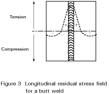
The intense heat associated with welding causes the region of the weld to expand. On cooling contraction occurs. This expansion and subsequent contraction is resisted by the surrounding cold material leading to a residual stress field being set up in the vicinity of the weld. Within the weld metal the residual stress tends to be predominantly tensile in nature. This tensile residual stress is balanced by a compressive stress induced in the parent metal [2]. A schematic view of the residual stress field obtained for longitudinal weld shrinkage is shown in Figure 3. The tensile residual stresses are up to yield point in magnitude in the weld metal and HAZ. It is important to note that the residual stresses arise because the material undergoes local plastic strain. This strain may result in cracking of the weld metal and HAZ during welding, distortion of the parts to be joined or encouragement of brittle failure during service.
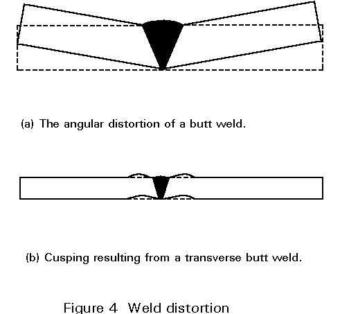
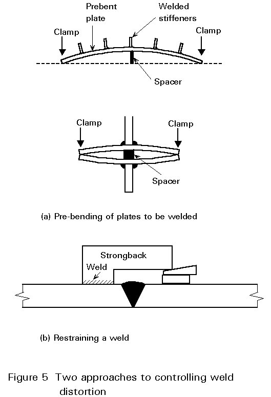
Transverse and longitudinal contractions resulting from welding can lead to distortion if the hot weld metal is not symmetrical about the neutral axis of a fabrication [2]. A typical angular rotation in a single V butt weld is shown in Figure 4a. The rotation occurs because the major part of the weld is on one side of the neutral axis of the plate, thus inducing greater contraction stresses on that side. This leads to a distortion known as cusping in a plate fabrication, as shown in Figure 4b. Weld distortion can be controlled by pre-setting or pre-bending a joint assembly to compensate for the distortion or by restraining the weld to resist distortion. Examples of both these methods are shown in Figure 5. Distortion problems are most easily avoided by using the correct weld preparation. The use of non-symmetrical double sided welds such as those shown in Figure 2e and 2i accommodates distortion. The distortion from the small side of the weld (produced first) is removed when the larger weld is put on the other side. This technique is known as balanced welding.
It is not possible to predict accurately the distortion in a geometrically complicated fabrication, but one basic rule should be followed. This rule is that welding should preferably be started at the centre of a fabrication and all succeeding welds be made from the centre out, thus encouraging contractions to occur in the free condition.
If distortion is not controlled, there are two methods of correcting it; force and heat. The distortion of light sections can be eliminated simply by using force, e.g. the use of hydraulic jacks and presses. In the case of heavier sections, local heating and cooling is required to induce thermal stresses counteracting those already present.
The most common and efficient way of relieving residual stresses is by heating. Raising the temperature results in a lower yield stress and allows creep to occur. Creep relieves the residual stresses through plastic deformation. Steel welded components are usually heated to a low red heat (600°C) during stress relieving treatments. The heating and cooling rates during this thermal stress relief must be carefully controlled otherwise further residual stress patterns may be set up in the welded component. There is a size limit to the structures which can be thermally stress relieved both because of the size of the ovens required and the possibility of a structure distorting under its own weight. It is possible, however, to heat treat individual joints in a large structure by placing small ovens around the joints or by using electric heating elements.
Other methods of stress relief rely on thermal expansion providing mechanical forces capable of counteracting the original residual stresses. This technique can be applied in-situ but a precise knowledge of the location of the compressive residual stresses is vital, otherwise the level of residual stress may be increased rather than decreased. Purely mechanical stress relief can also be applied provided sufficient is available to accommodate the necessary plastic deformation.
If weld preparation is good and operator induced defects (e.g. lack of penetration or fusion) are avoided, all the common structural steels can be successfully welded. However, a number of these steels may require special treatments to achieve a satisfactory joint. These treatments are not convenient in all cases. The difficulty in producing satisfactory welded joints in some steels arises from the extremes of heating, cooling and straining associated with the welding process combined with microstructural changes and environmental interactions that occur during welding. It is not possible for some structural steels to tolerate these effects without joint cracking occurring. The various types of cracking which can occur and the remedial measures which can be taken are discussed below.
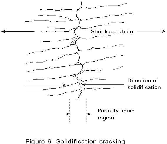
Solidification of the molten weld pool occurs by the growth of crystals away from the fusion boundary and towards the centre of the weld pool, until eventually there is no remaining liquid. In the process of crystal growth, solute and impurity elements are pushed ahead of the growing interface. This process is not significant until the final stages of solidification when the growing crystals interlock at the centre of the weld. The high concentration of solute and impurity elements can then result in the production of a low freezing point liquid at the centre of the weld. This acts as a line of weakness and can cause cracking to occur under the influence of transverse shrinkage strains. Impurity elements such as sulphur and phosphorus are particularly important in this type of cracking since they cause low melting point silicides and phosphides to be present in the weld metal [3]. A schematic view of solidification cracking is shown in Figure 6.
Weld metals with a low susceptibility to solidification cracking (low sulphur and phosphorous) are available for most structural steels, but cracking may still arise in the following circumstances:
a. If joint movement occurs during welding, e.g. as a result of distortion. A typical example of this is welding around a patch or nozzle. If the weld is continuous, the contraction of the first part of the weld imposes a strain during solidification of the rest of the weld.
b. If contamination of the weld metal with elements such a sulphur and phosphorus occur. A typical example of this is the welding of articles with a sulphur rich scale, such as a component in a sulphur containing environment.
c. If the weld metal has to bridge a large gap, e.g. poor fit-up. In this case the depth to width ratio of the weld bead may be small. Contraction of the weld results in a large strain being imposed on the centre of the weld.
d. If the parent steel is not suitable in the sense that the diffusion of impurity elements from the steel into the weld metal can make it susceptible to cracking. Cracking susceptibility depends on the content of alloying element with the parent metal and can be expressed in the following equation:
Hot cracking susceptibility = ![]()
Note: The higher the number, the greater the susceptibility.
Solidification cracking can be controlled by careful choice of parent metal composition, process parameters and joint design to avoid the circumstances previously outlined.
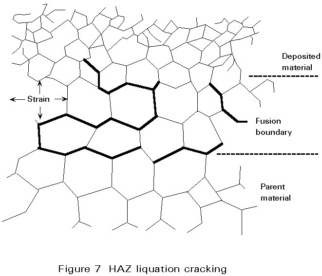
The parent material in the HAZ does not melt as a whole, but the temperature close to the fusion boundary may be so high that local melting can occur at grain boundaries due to the presence of constituents having a lower melting point than the surrounding matrix. Fine cracks may be produced in this region if the residual stress is high. These cracks can be extended by fabrication stresses or during service [3]. A schematic view of liquation cracking is shown in Figure 7.
In steels the low melting point grain boundary films can be formed from impurities such as sulphur, phosphorus, boron, arsenic and tin. As with solidification cracking, increased carbon, sulphur and phosphorous make the steel more prone to cracking.
There are two main ways of avoiding liquation cracking. First, care should be taken to make sure that the sulphur and phosphorus levels in the parent metal are low. Unfortunately, many steel specifications permit high enough levels of sulphur and phosphorus to introduce a risk of liquation cracking. Secondly, the risk of liquation cracking is affected by the welding process used. Processes incorporating a relatively high heat input rate, such as submerged arc or electroslag welding, lead to a greater risk of liquation cracking than, for example, manual metal arc welding. This is the case since the HAZ spends longer at the liquation temperature (allowing greater segregation of low melting point elements) and there is a greater amount of thermal strain accompanying welding.
This form of cracking (also known as HAZ, underbead, cold or delayed cracking) occurs in the HAZ at temperatures less than 200°C. Cracks can form within minutes of welding or be delayed for several days. Three factors must co-exist if cracking is to occur. These factors are:
a. The presence of hydrogen
Hydrogen is introduced into the molten weld pool during welding as a result of the decomposition of hydrogen containing compounds in the arc, e.g. moisture, grease paint and rust. Once the gas has dissolved in the weld metal, it can diffuse rapidly into the HAZ both during cooling and at ambient temperatures. In due course, the hydrogen will diffuse out of the steel. The diffusion can take a period of weeks for a thick-walled vessel.
b. A susceptible weld metal or HAZ
The cooling rate following most fusion welding processes is relatively rapid. This cooling can lead to the formation of martensite or other hardened structures in the HAZ and possibly the weld metal. These structures can be embrittled by the presence of only small quantities of hydrogen.
c. A high level of residual stress after welding.
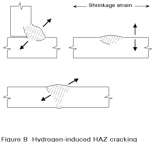
Cracking develops under the action of the residual stresses from welding in the susceptible microstructure of the HAZ or weld metal, where embrittlement has occurred due to the presence of hydrogen in solution [3]. A schematic view of hydrogen cracking in the HAZ of different weld designs is illustrated in Figure 8.
The methods of avoiding hydrogen cracking involve removing or limiting one of the three factors which are necessary for it to occur. Hydrogen cracking can be avoided by choosing a material which does not harden in the HAZ or weld metal with the particular welding process employed. The likelihood of hardening in the HAZ is controlled by the cooling rate after welding and the hardenability of the parent steel. The hardenability of a steel is governed by its composition. A useful way of describing hardenability is to assess the total contribution to it of all the elements that are present in the steel. This assessment is done by an empirical formula which defines a carbon equivalent value (CEV) and takes account of the important elements which affect hardenability. A typical formula for the CEV (accepted in British Standards) is shown below:
CEV = ![]()
As a general rule, hardening in the HAZ can be avoided by using a steel with a CEV of less than 0,42 although it should be noted that the welding process parameters influence this value.
Increasing the heat input rate of the welding process (where possible) is beneficial since it results in a slower cooling rate after welding and therefore a lower likelihood of hardening in the HAZ. For the same reason, there is a less risk of hydrogen cracking when welding thin plates and sections, since the cooling rate in the HAZ is less than in thick sections.
Limiting the presence of hydrogen by avoiding damp, rust and grease, by using controlled hydrogen electrodes (properly dried basic coated electrodes) and low hydrogen welding processes (MIG or submerged arc welding) is another step towards avoiding cracking.
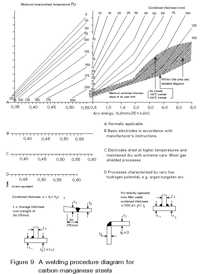
If these precautions are not sufficient, preheating is necessary. Preheating and the maintenance of a minimum interpass temperature during multi-pass welding has two effects. First, it results in softening of the HAZ because the cooling rate is reduced. Secondly, it accelerates the diffusion of hydrogen from the weld zone so that less remains after the weld has cooled. The minimum pre-heat temperature required to avoid hydrogen cracking depends on the chemical composition of the steel, the heat input rate and the thicknesses being joined.
The minimum pre-heat temperature can be calculated by interrelating these facts in a welding procedure diagram [3]. An example of one of these diagrams for carbon manganese steels is shown in Figure 9. This diagram is used in the following way:
This problem can arise if the residual stresses from welding are applied across the thickness of at least one of the plates being joined [3]. Cracking occurs if the through-thickness ductility of the plate is very low. A schematic view of this mode of cracking is shown in Figure 10.
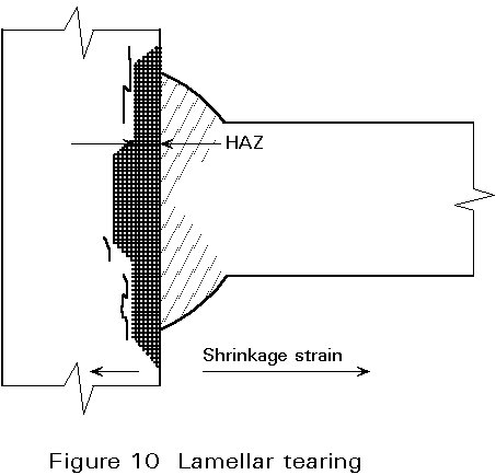
Cracking normally occurs in the parent metal close to the outer boundary of the HAZ. The cracks have a characteristic stepped appearance with the 'threads' of the steps being parallel to the rolling direction of the steel plate. In contrast to hydrogen cracking, lamellar tears are not necessarily confined to the HAZ. In some cases, cracking can occur at the mid-thickness of a plate if it is restrained by a weld on both sides.
Lamellar tearing arises because the through-thickness ductility of the plate is reduced by the presence of planar inclusions lying parallel to the plate surface. All common structural steels contain large numbers of inclusions which consist of non-metallic substances produced in the steelmaking process, e.g. sulphates and silicates. These inclusions are formed as spheres, grain boundary films, or small angular particles in the steel ingot as it cools down after casting. When the ingot is rolled to make steel plate the inclusions deform into discs parallel to the plate surface. Different types of inclusions deform in different ways and break up during rolling. The form, distribution and density of inclusions in a rolled plate determine the through-thickness ductility. Only a small proportion of steel plates have a sufficiently low through-thickness ductility to be susceptible to lamellar tearing.
Lamellar tearing can be avoided in four main ways:
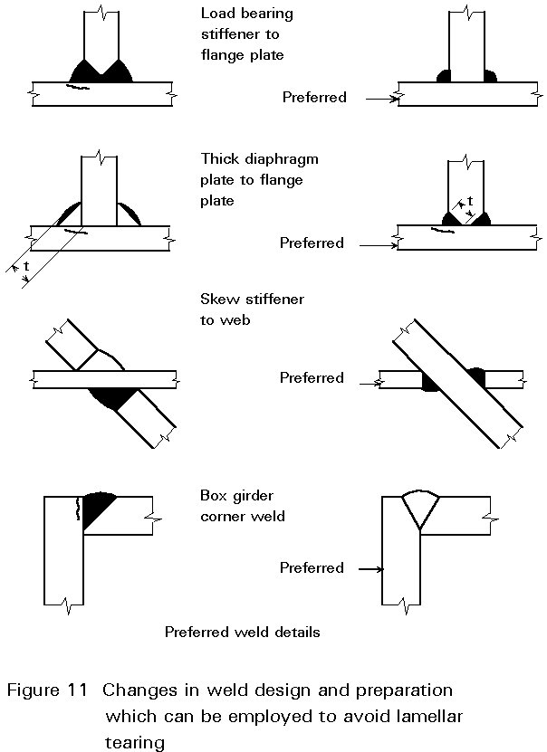
a. Improved joint design
The design of a fabrication can be altered to avoid residual stresses in the through-thickness direction of a plate. Examples are shown in Figure 11.
b. The use of forged products
The lamellar distribution of inclusions in a plate is a result of the plastic deformation occurring during rolling. The inclusion distribution in forged products is not so detrimental.
c. Plate selection
The use of steel plates with a relatively low population of planar inclusions and thus adequate through-thickness ductility.
d. Using a layer of low strength weld metal
This reduces the strain transmitted through the thickness of the welded steel plates since the soft weld metal can deform plastically. This technique, known as 'buttering' is relatively expensive but can be used when susceptible joints cannot be avoided.
The removal or reduction of residual stresses after welding by thermal stress relief is recommended for many fabrications. In this process, the joint reaches a temperature range where rapid creep can occur (about a third to a half of the melting point). As a result, the welding residual stresses are relieved by plastic deformation. Cracking can occur during this process if the ductility of the weld or HAZ is not sufficient to accommodate the strain accompanying the residual stress relief [3]. A schematic view of re-heat cracking is shown in Figure 12.
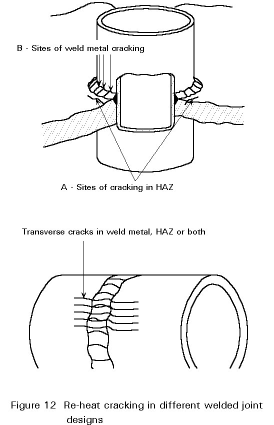
The residual tensile stress which acts as the driving force for the cracking process may be supplemented by transient thermal stresses in the weld zone. These stresses arise from rapid non-uniform heating up to the stress relieving temperature. The presence of geometric stress raisers, e.g. toes of fillet welds, and pre-existing cracks, e.g. liquation and hydrogen cracks, accentuate the problem.
The cracking problem is most prevalent during stress relieving operations, but it can also occur in service situations. In such cases the onset of cracking is expected to take much longer since the service temperature is generally significantly below the stress relieving temperature.
Re-heat cracking is mainly confined in practice to alloy steels containing substantial amounts of strong carbide forming elements, e.g. Cr, Mo and V. The presence of the alloy carbides inhibits grain boundary sliding and thus reduces high temperature ductility. Cracking can usually be avoided by weld profiling, e.g. grinding away any geometric stress raisers such as the toes of fillet welds, before heat treatment and by control of the heating rate to avoid high transient thermal stresses.
[1] Hicks, J. G., "Welded Joint Design", BSP Professional Books, 1979.
[2] Pratt, J. L., "Introduction to the Welding of Structural Steelwork", Steel Construction Institute, 3rd rev. ed. 1989.
[3] Baker, R. G., "The Welding of Pressure Vessel Steels", The Welding Institute, 1973.