ESDEP WG 8
PLATES AND SHELLS
To describe the main features and advantages of box girders; to introduce the methods of global analysis; to describe aspects of behaviour particular to box girders.
Lecture 6.1: Concepts of Stable and Unstable Elastic Equilibrium
Lecture 8.1: Introduction to Plate Behaviour and Design
Lectures 8.4: Plate Girder Behaviour and Design
Lecture 8.5.2: Advanced Design of Box Girders
A general overview is given of the form and behaviour of box girders. Typical configurations are illustrated and the advantages of box girders over plate girders are highlighted. The structural behaviour of box sections is described; global analysis is discussed; the particular features of the design of webs and flanges are introduced; the function and form of cross sectional restraints. including diaphragms, are described.
A box girder is formed when two web plates are joined by a common flange at both the top and the bottom. The closed cell which is formed has a much greater torsional stiffness and strength than an open section and it is this feature which is the usual reason for choosing a box girder configuration.
Box girders are rarely used in buildings (box columns are sometimes used but these are axially loaded rather than in loaded in bending). They may be used in special circumstances, such as when loads are carried eccentrically to the beam axis.
Steel and composite box girders are used for highway bridges, though they are most expensive than plate girders (because fabrication requires more time and effort).
The use of box girders for bridges offers the following advantages over plate girders:
Torsional rigidity is particularly advantageous when the girder needs to be curved in plan. A box section can carry the torsion resulting from vertical loading without the need for lateral bracing.
The use of wide flanges facilitates the choice of shallow construction depth (that is, a large span-to-depth ratio) which may be desirable when space or headroom is restricted. Shallower girders will be heavier but this may be a lesser consideration in such circumstances.
Any stiffening needed to the webs and flanges can usually be arranged inside the box section. The clear external surfaces offer a neater, more pleasing, appearance and avoid the corners and crevices which are difficult to protect adequately against corrosion.
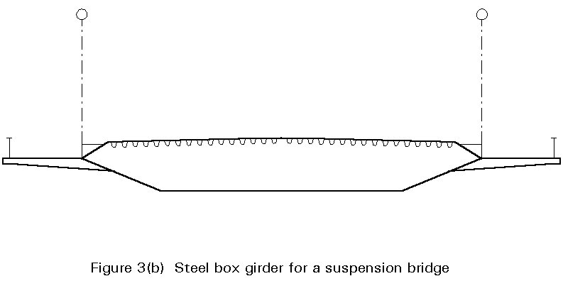
The use of inclined webs (closer together at the bottom than at the top) reduces the width of the bottom flange plate (often advantageous to structural performance, particularly when the flange is in compression). Inclined faces are frequently considered to give a better appearance than vertical faces. Inclined webs also offer better aerodynamic performance. The cross-sectional shape of the box girders of many long-span cable-stayed and suspension bridges are chosen after wind-tunnel testing to find the shape which offers minimum drag and optimum dynamic response.
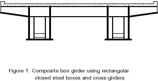
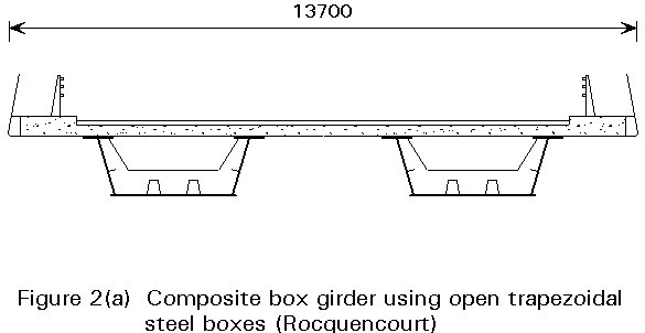
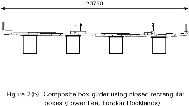
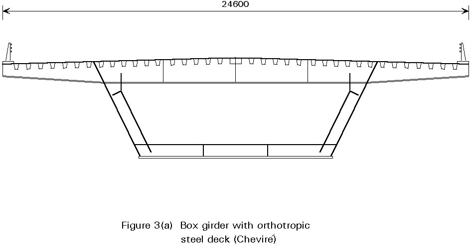
Box girder bridges are constructed with single, twin or multiple box girders. The deck of the bridge may be of reinforced concrete or it may be a stiffened steel deck. When reinforced concrete is used the steel girders may be closed box sections or may be open sections (U-shaped) which are closed when the slab is cast across the top. A selection of configurations is shown in Figures 1 - 3.
The method of erection is often an important factor in choosing a cross-section for a box girder bridge. The torsional stability of the box section avoids the need for temporary bracing (such as is needed with plate girders). The bridge can be built by lifting consecutive pre-assembled units of the complete cross section and joining them end-to-end. This is particularly suitable for cantilever erection of long spans.
Many of the features of box girders illustrated in Figures 1, 2 and 3 are similar to those of plate girders, though the proportions may be different. There are a few features which are particular to box girders.
Web plates carry shear forces and bending moments. Thin webs need transverse stiffeners to achieve adequate resistance, in the same way as they do in plate girders. Inclined webs are deeper (in their planes) and may therefore require more stiffening.
Flange plates connecting two webs are wider than those of corresponding I-beam girders. Consideration must be given to shear lag. When the flange plate is in compression its stability (against out-of-plane buckling) must be considered; longitudinal and transverse stiffeners are frequently necessary.
When open steel sections are used, made into composite box girders by a concrete deck slab, separate (and relatively small) flange plates are provided at the top of each web. These flanges need to be stabilised laterally by bracing during construction. Shear connection on the top of the flanges is similar to that on the flanges of I-beam girders.
When closed steel boxes are used, overlaid by a reinforced concrete slab to form a composite section, shear connection is required over the full width of the top flanges.
When the bridge deck is steel, the top flanges are stiffened orthotropically to carry wheel loads from traffic as well as acting as a box girder flange. This stiffening usually takes the form of longitudinal trough stiffeners supported at regular intervals by transverse beams.
At supports plated diaphragms are provided. At each support there are one or two bearings, located between the webs and directly below the diaphragms. The diaphragms serve to transfer the load from the webs to the bearings (generally acting as a deep beam) and to prevent distortion of the section.
In all except smaller boxes restraint against distortion is also required at intermediate positions; this can be achieved with braced cross-frames, stiff ring frames or plated diaphragms.
Access inside box sections is necessary during construction and during the life of the structure. Manholes must be provided in support and intermediate diaphragms, to permit passage along the length of the box; the size and location of the holes is taken into account in the design of the diaphragm.
As for I-beam girders, global analysis determines the bending moments and shears in the main beams due to the applied loading. Since the principal loads are vertical, greatest attention is given to moments and shears in the vertical plane, though horizontal loading and effects must also be considered.
However, when box girders are used, two additional effects must be considered, torsion and distortion. As we shall see later, consideration of distortional effects may be limited to local regions between intermediate diaphragms. Torsional effects must be determined by the global analysis.
For a single straight uniform section girder any simple line beam analysis would suffice for bending, shear and torsional effects, but in general the most appropriate model for evaluating the effects due to vertical loading is the grillage analogy. Beam elements in a grillage model have three degrees of freedom - vertical deflection, rotation about a transverse axis and rotation about a longitudinal axis - and are thus able to determine directly the three principal effects which are to be considered in the stress analysis. Computer programs are available specifically for grillage analysis, though many designers make use of general purpose space-frame programs (in which the elements have the full 6 degrees of freedom).
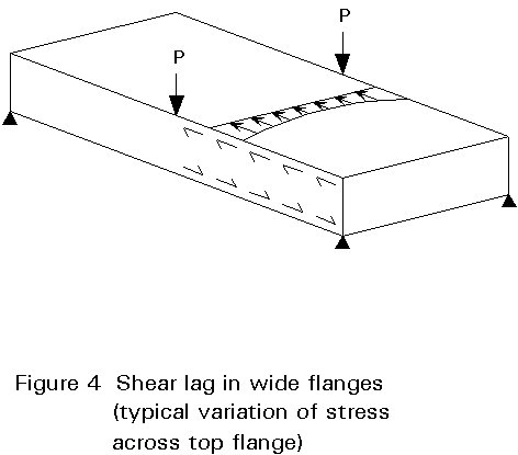
In very wide flanges shear lag effects must be taken into account. When the axial load is fed into a wide flange by shear from the webs the flange distorts in its plane; plane sections do not remain plane. The resulting stress distribution in the flange is not uniform (see Figure 4). This effect is not taken into account in a grillage analysis and must be separately determined.
The calculation of distortional effects, which include transverse bending stresses and longitudinal warping stresses can be carried out by methods based on beam-on-elastic-foundation analogy. Where stiff intermediate cross-frames or diaphragms are provided the stresses are usually quite small.
In very complex configurations finite element analysis might be used. Shell elements are connected to model the complete cross-section along the whole length of the girder. Provided that the mesh is sufficiently fine and the element behaviour is appropriate, effects such as warping, distortion and shear lag are determined at the same time as the principal bending, shear and torsion effects.
Folded plate analysis is sometimes used, but it is only appropriate when the box section is uniform along its length, when there are no intermediate cross-frames and when the loading can be represented by harmonic series. It is difficult to apply to ordinary design situations.
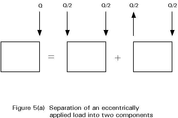
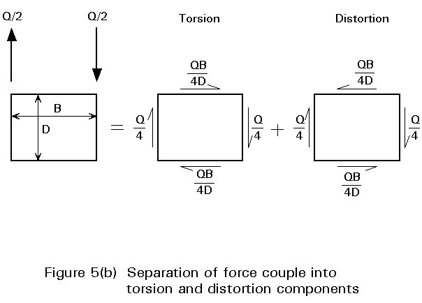
The general case of an eccentric load applied to a box girder is in effect a combination of three components - bending, torsion and distortion. As a first step, the force can be separated into two components, a pair of symmetric vertical loads and a force couple, as shown in Figure 5(a). However, torsion is in fact resisted in a box section by a shear flow around the whole perimeter and the couple should in turn be separated into two parts, representing pure torsion and distortion, as shown in Figure 5(b).
The first two components, vertical bending loads and a torsional shear flow, are externally applied forces, and they must be resisted in turn at the supports or bearings. The third component, distortional forces, comprises an internal set of forces, statically in equilibrium, which do not give rise to any external reaction. Distortional effects depend on the behaviour of the structure between the point of application and the nearest positions where the box section is restrained against distortion.
The theoretical behaviour of a thin-walled box section subject to pure torsion is well known and is treated in many standard texts. For a single cell box, the torque is resisted by a shear flow which acts around the walls of the box. This shear flow (force/unit length) is constant around the box and is given by q = T/2A, where T is the torque and A is the area enclosed by the box. (In Figure 2 the torque is QB/2 and the shear flow is Q/4D.) The shear flow produces shear stresses and strains in the walls and gives rise to a twist per unit length, q , which is given by the general expression:
![]() or,
or, ![]()
where J is the torsion constant.
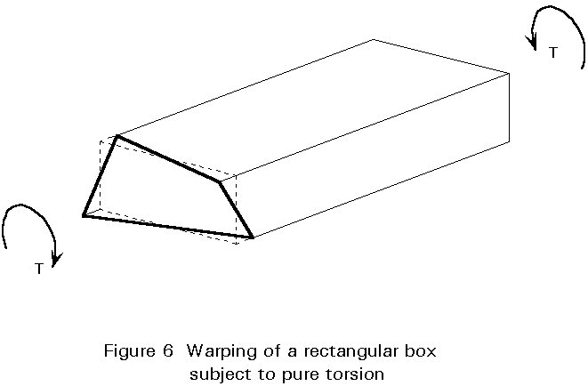
However, it is less well appreciated that this pure torsion of a thin walled section will also produce a warping of the cross-section, unless there is sufficient symmetry in the section. This is illustrated in Figure 6 for a rectangular section that is free to warp at its ends. However, in practice boxes are not subject to pure torsion; wherever there is a change of torque (at a point of application of load or at a torsional restraint) there is restraint to warping, because the 'free' warping displacements due to the different torques would be different (restraint is high, for example. over intermediate supports where torsion is restrained). Such restraint gives rise to longitudinal warping stresses and associated shear stresses in each wall of the box.
When torsion is applied directly around the perimeter of a box section, by forces exactly equal to the shear flow in each of the sides of the box, there is no tendency for the cross section to change its shape. Torsion can be applied in this manner if, at the position where the force couple is applied, a diaphragm or stiff frame is provided to ensure that the section remains square and that torque is in fact fed into the box walls as a shear flow around the perimeter.
Provision of such diaphragms or frames is practical, and indeed necessary, at supports and at positions where heavy point loads are introduced. But such restraint can only be provided at discrete positions. When the load is distributed along the beam, or when point loads can occur anywhere along the beam such as concentrated axle loads from vehicles, the distortional effects must be carried by other means.
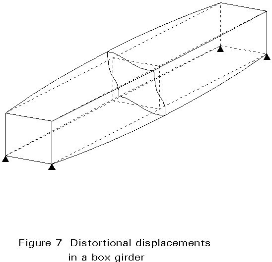
The distortional forces shown in Figure 5(b) are tending to increase the length of one diagonal and shorten the other. This tendency is resisted in two ways, by in-plane bending of each of the wall of the box and by out-of-plane bending. this is illustrated in Figure 7.
In general the distortional behaviour depends on interaction between the two sorts of bending. The behaviour has been demonstrated to be analogous to that of a beam on an elastic foundation (BEF), and this analogy is frequently used to evaluate the distortional effects.
If the only resistance to transverse distortional bending is provided by out-of-plane bending of the flange plates there were no intermediate restraints to distortion, the distortional deflections in most situations would be significant and would affect the global behaviour. For this reason it is usual to provide intermediate cross-frames or diaphragms; consideration of distortional displacements and stresses can then be limited to the lengths between cross-frames.
Tension flanges are designed mainly on the basis of longitudinal bending stresses, in the same way as for plate girders. Torsional and distortional effects and the effects of shear lag do need to be taken into account in some circumstances. The strength is taken as the yield stress.
At the Serviceability Limit State elastic behaviour is normally specified. Then the stresses due to the restraint of torsional warping, distortional warping stresses and the variation of stress across the flange due to shear lag must be calculated. Stresses are highest adjacent to the web.
At the Ultimate Limit State, plastic behaviour is normally accepted. Then the stresses due to the restraint of torsional warping and shear lag can be neglected, since they are secondary effects.
In addition to considering the load effects in relation to yield strength, the stability of the compression flange must also be considered.
Relatively narrow flanges may be unstiffened. The strength of the flange plate then depends on ordinary panel-buckling resistance. It is convenient to express this in design by the determination of an effective width of compression flange; this is the width which has the same resistance, at yield stress, as the buckling resistance of the full panel. Typically a panel is considered fully effective up to a width of 24t (where t is the flange thickness), but thereafter the effective width is less than the actual width.
Wider flanges are provided with longitudinal stiffeners to provide stability and these in turn are supported at intervals by transverse stiffeners, cross-frames, or diaphragms.
Usually the longitudinal stiffeners can be designed using rules which effectively treat them as struts. For this purpose the transverse members restraining them must be sufficiently stiff. If, when the flanges are particularly wide, the transverse stiffeners are not sufficiently stiff, the flange would have to be treated as a panel stiffened in two directions and the overall buckling strength determined; this is too complex for most design purposes.
In some bridges, notably long-span bridges and movable bridges, where minimum weight is desirable, the roadway is carried on an all-steel deck. This form of deck is stiffened longitudinally; transverse members or diaphragms support the longitudinal stiffeners.
The design of such a deck, to carry the direct loads from the traffic wheels, is an extremely complex matter. Connection details are subject to onerous fatigue loading. Configurations currently in use are the result of many years development, analysis, testing and feedback from previous designs.
The determination of the strength of webs in bending and shear follows the same general rules as for plate girders.
Shear buckling resistance of thin webs is improved by the presence of intermediate stiffeners. Tension field action can develop in the web in the same way as in plate girders. However, the further increase in tension field action on account of the bending stiffness of the flange plate is not normally achievable.
The main functions of cross sectional restraints are:
At support positions a plate diaphragm is normally provided, see Figure 8, although occasionally a heavily braced frame can be used. Plate diaphragms may be thick and unstiffened in fairly small boxes; in larger boxes vertical stiffeners are provided over the bearings and sometimes horizontal stiffening is also provided.

The main purpose of support diaphragms is to transfer the large shear forces from the webs to the bearings. They must also transmit horizontal forces when the bearing is guided or fixed in position into shear flow along the web of the box section.
For large box sections, with large support forces, the use of a finite element program is recommended for the design of support diaphragms.
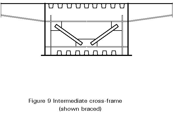
For large deep box girders, intermediate restraint against distortion is usually provided by cross frames, see Figure 9. The frame comprises a ring of four members, each being an effective section comprising a width of flange or web and the transverse stiffener attached to it. The corners of the ring need to be designed to provide moment continuity. Diagonal bracing is connected to the frame as necessary, usually either across the section diagonal or as a V to the midpoint of a flange stiffener.
When a box girder has a stiffened steel deck, or a composite box girder is arranged with cross-girders, such that the deck slab designed to span longitudinally, the transverse stiffeners must also carry the traffic loads and transfer them to the webs. Such configurations usually also have cantilevers on the outer faces. Moment continuity must be provided between the transverse stiffeners, the cantilevers and the cross-girders.
Transverse flange stiffeners which are required to provide support must usually be arranged to coincide with transverse web stiffeners, so that the load can be transferred into the web.
The arrangement of the bearings which support the girder, known as the articulation arrangement, should take account of the high degree of torsional rigidity provided by the box girders.
For a relatively short bridge of a few spans it is not necessary to provide two bearings at each intermediate support. Twin bearings at the ends will restrain the box against twist; single bearings on the box centreline are sufficient at intermediate supports.
If the bridge is highly curved, single bearings may be sufficient at all supports; restraint against twist is provided by the combined effects of torsional rigidity and geometrical arrangement of the group of bearings.