ESDEP WG 15B
STRUCTURAL SYSTEMS: BRIDGES
To provide general information on splices and other connections in bridges and to present guidelines for their analysis and design.
None.
Lectures 1B.6: Introduction to Design of Steel and Composite Bridges
Lectures 3.1: General Fabrication of Steel Structures
Lectures 3.2: Erection
Lecture 3.6: Inspection/Quality Assurance
Lecture 4A.4: Corrosion Protection of Bridges
Lecture 11.1.2: Introduction to Connection Design
Lectures 11.2: Welded Connections
Lecture 11.3.2: Connections with Preloaded Bolts
Lectures 11.4: Analysis of Connections
Lecture 11.8: Splices
Lecture 12.1: Basic Introduction to Fatigue
Lecture 12.6: Fatigue Behaviour of Bolted Connections
Lecture 12.8: Basic Fatigue Design Concepts in Eurocode 3
Lectures 15B: Structural Systems: Bridges
The various methods used for making splices and other connections in bridges are discussed and guidance is given on their design. The connections used in particular bridge members are described. Attention is drawn to the special considerations that apply when fatigue could influence the design.
Apart from the simplest of bridges, with relatively short spans, the main girders of bridges are made up of elements connected together in the fabricating shop. For example, a plate girder is normally fabricated by welding together top and bottom flanges, web plates and stiffeners. A lattice girder is fabricated from top and bottom chords with internal diagonal (and vertical) members.
Normally, as much of the fabrication as possible is carried out in the fabricating shop. However, due to limitations on the size of the pieces that can be transported from the fabricating shop to the site, or possibly due to access problems or limitations on the weight that can be lifted into position, most bridges consist of a number of sub-assemblies connected together on site. It is the connections between these sub-assemblies that are the subject of this lecture.
Site connections, referred to as splices, are required between sections of the main girders where these cannot be delivered to site and erected in one piece. They are also required to connect the secondary members, e.g. to connect the cross girders to the main girders and to connect any bracing that is required.
The location of splices has a major influence on the economics of the design, fabrication and erection of bridges. In addition, the detailing of splices influences the fatigue and corrosion resistance of a bridge.
The designer must always, from initial concept through design and analysis to final detailing of the bridge, keep the connections in mind. At all stages he must know where the connections will be, how they will be designed and detailed, how they will be fabricated and when they will be fitted together.
The relative position and orientation of the elements to be joined can make the difference between a straightforward, effective connection and one that is difficult to design, detail, fabricate and erect. It is for this reason that the connections should be considered at an early stage in the design process.
A significant part of the cost of a structure is attributable to the connections. It may, for example, be sensible to alter the depth of a member, such as a cross girder, if this enables a simpler end connection to be used, even if this increases the weight of the member.
There are two basic methods of making splices. Welding, using butt welds or fillet welds, and bolting. Where the main elements of the splice can be connected together with full strength butt welds, the design is simple and the effect of any loss of section due to the bolt holes does not arise.
When making a decision as to whether welding or bolting is to be used, the following are some of the points that should be considered:
In addition to the pre-planning and care that is required to deal with the problems of temporary support, access, location and good fit, consideration must also be given to the potential effects of weld shrinkage.
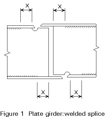
These points can be illustrated by reference to the staggered connection shown in Figure 1. Alignment of the flange can be helped by omitting the flange-to-web welds for a short distance X on either side of the connection before assembly. The flange-to-web welds are completed after the other welds.
One method of reducing the effects of the shrinkage of the transverse welds is to complete the flange welds before carrying out the web welds. Due to the slenderness of the web, the shrinkage of the flange welds could cause buckling of the web if it is welded first. An alternative procedure is to make individual runs of weld on the flanges and web in sequence, starting with the flanges. This should tend to balance the shrinkages between the elements.
The cope holes in the web adjacent to the flange welds improve the access for welding the flanges and should result in a better stress pattern. Normally, the cope hole should not be filled in, although filling may be necessary for corrosion protection in box girders.
Untorqued, bearing bolts in normal (2mm) clearance holes are not generally used for splices in bridges. In most splices the deformation associated with slip into bearing would be unacceptable. To avoid the slip, fitted bolts, in close tolerance holes, or High Strength Friction Grip (HSFG) bolts are required. Generally HSFG bolts are used, since this avoids the need to match and ream the holes. The pretensioning of the bolts also improves their fatigue life and prevents the nuts working loose due to vibration.
It is important that, when HSFG bolts are to be used, adequate clearances are provided to allow the use of suitable tightening tools.
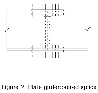
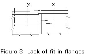
A typical bolted cover plate splice is illustrated in Figure 2. It is possible that variations in the profiles of the two parts of the girder may occur due to rolling tolerances, differences in the overall depths and relative twisting or warping of the flanges. This may result in a mismatch such as that illustrated in Figure 3. The possibility of this occurring should be considered in the design of the splice and in the corrosion protection. Adding extra bolts, at the detailing stage, is a simple way of ensuring that the slip resistance would still be adequate if a mismatch should occur.
Shims or packs are used, for example, where there is a change of flange plate thickness. It is essential that the surfaces of the packs or shims comply with the requirements assumed for the faying surfaces in the design.
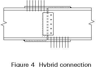
A combination of welds and bolts could be used in a splice. A possible hybrid connection, for a light beam, is illustrated in Figure 4. In this splice the cover plates are each attached to one half of the beam in the fabricating shop and the bolting is used to complete the splice on site. One disadvantage of the connection is that each part requires both drilling and welding in the fabrication shop.
If a combination of different types of bolt or of bolts and welds, with different load/deformation characteristics, is used in the same part of a connection, the load will tend to be carried by the stiffer connecting elements. Consequently, one type of bolt or weld should be assumed to transmit all of the load. An example of this would be if a bolted cover plate, using bolts in clearance holes, were to be "strengthened" by fillet welding the cover plate to the flange. The bolts would be ignored and the weld would have to be designed to carry all the load. There is an exception to this rule which is that HSFG bolts designed as slip resistant at the ultimate limit state may be assumed to share the load with welds, provided that the final tightening of the bolts is carried out after the welding is complete.
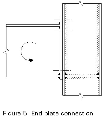
The most straightforward procedure for the design of a connection is to consider the load paths by which the forces are transmitted through the connection. For example, in the end plate connection illustrated in Figure 5, the tensile force in the top flange of the beam is transmitted through the following load path: beam flange in tension - fillet welds in shear - end plate in bending-bolts in tension-flange of vertical member in bending-flange to web fillet welds in shear-web of vertical member. Similarly, the load path followed by the compressive force in the bottom flange is: beam flange in compression-end plate and flange of vertical member in bearing/compression-stiffeners in compression and shear-stiffener fillet welds in shear-vertical member.
The load paths through a connection must be sufficient to carry all the applied forces, moments and shears. The load paths must be complete and in equilibrium, i.e., there must be no weak or missing links. They should be as direct as possible.
Care is required to ensure that the worst combinations of moments and forces that can occur at the connections are used for their design. They are not necessarily the moment and forces used for the design of the members. It follows that the moments and forces supplied by a computer program for the design of the members may not be sufficient for the design of the connections.
The centroidal axes of members (and elements of members) should intersect wherever possible. If it is not possible, the effects of any eccentricity should be taken into account in the design.
Wherever practicable, the centroidal axis of the splice material should coincide with the centroidal axis of the elements joined. Where it is not possible, the effect of any eccentricity should be considered in the design.
Avoid severe stress concentrations. This is particularly important where fatigue could be a problem.
Consider the effect of any lack of fit on the behaviour of the connection, particularly in regard to the effect it could have on the fatigue life of the connection.
There are many types of steel bridge, e.g. simple beams, plate girders, portal girders, trusses (Pratt, warren and bowstring), arches, cable-stayed bridges and suspension bridges. In addition, there are variations such as the use of composite deck construction.
The basic principles of connection design apply to all types of bridge. It is not possible to cover specific details for all the different bridges in one lecture. However, additional guidance for some of the more common splices is given below.
Generally, the splices in beams and plate girders are made with bolted cover plates using HSFG bolts. Alternatively, welded splices may be used, particularly where a clean appearance is required.
When the beams are continuous, the splices are usually positioned near to where the point of contraflexure (zero moment) would be if the bridge were subjected to uniform loading. The maximum moment (and shear) that the splice can be subjected to under the possible loading patterns must be determined. If redistribution of moments (plastic design) has been used for the beam design, then the moment at the splice assuming an elastic design should also be checked since, if the yield of the beam is above the minimum or the section is heavier than the minimum required, the plastic redistribution may not take place. It would be undesirable for the splice to be required to act as a plastic hinge. If the design moment is relatively low it would be wise to design the splice to transmit a moment of at least, say, one third of that which produces yield in the extreme fibre. A similar minimum strength should apply to the shear resistance.
Trusses for relatively short spans are usually shop welded, with a minimum number of site joints. Footbridges and conveyor bridges are frequently fabricated from hot rolled hollow sections, in which case welding is the only reasonable procedure for making the joints in the fabrication shop. If site joints are necessary they can be welded, or bolted flanges may be used if they are aesthetically acceptable.
Larger span trusses, where the overall depth is greater than the depth/width that can be transported, are usually fabricated with bolted joints for assembly on site. Gusset plates are often used at the connection to simplify the erection and to enable the centroidal axes of the members to meet at a single point.
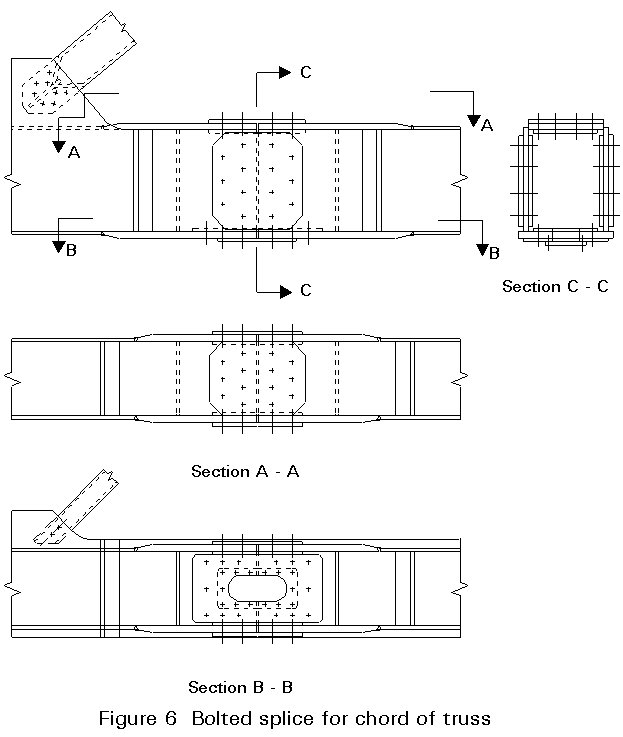
Fabricated box sections are often used for the chords of the larger span bridges. A bolted joint for such a chord is shown in Figure 6. The plates of the chord have been increased in thickness to compensate for the loss of section due to the bolt holes (and the access hole). The splice should not be in the most heavily loaded section of the chord and the alternative of carrying through thicker plates to the splice, to avoid the cost of the additional butt welds at the ends of the thickened plate, should be considered. An access hole is required to give access for placing the bolts. After use, it is sealed with a cover plate to give corrosion protection to the inside of the chord.
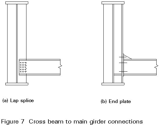
Two methods of connecting the cross beams to the main girders are shown in Figure 7. Neither detail would generate the full strength of the cross beam, but this would not normally be required (where there are only two main girders). In any splice, whether or not the plates can be drawn into full contact depends upon the accuracy of fabrication, the stiffness of the plates and the closing force applied by the bolts. The lapped spliced is the easiest to fabricate and erect. In the bolted end plate detail, the welded end plate is more likely to be distorted and there is less tolerance to allow for small errors in length or alignment. If , for example, there is an error in the relative vertical alignment of the end plates of adjacent cross girders, the pulling together of the plates is resisted by the torsional stiffness of the main girder and by the bending resistances of the cross beams, so that closure of the plates may not be possible. If the plates are not drawn together properly, the fatigue life of the HSFG bolts may be seriously reduced. A further alternative detail would be to weld a section of the cross beam to the main girder in the shop and use a cover plate splice to connect this to the main part of the cross beam on site.
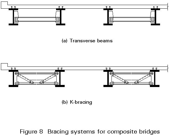
Bracing is usually required to give torsional and lateral restraint to the main girders. Two typical bracing systems for a composite construction bridge are shown in Figure 8. The girders are braced in pairs to avoid the additional stresses that would occur if continuous bracing, which would redistribute the loading between the girders, were used.
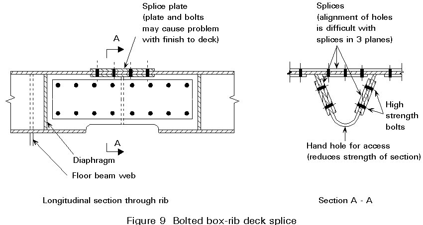
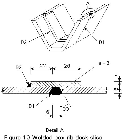
For splices in orthotropic decks, the deck plate, ribs and floor beams should be connected to provide one integral unit. The splices can be bolted or welded. Alignment of the details on site is a particular problem and careful fabrication and erection are required.
Bolted connections (Figure 9) tend to be more complex, but have the advantage that their completion on site is not so weather dependent. Welded splices (Figure 10) for such highly stressed elements of the deck should be made with particular care.
Where fatigue could be a consideration in the design of the bridge, it must be designed, detailed and fabricated so as to reduce or eliminate stress concentrations wherever possible. The allowable stresses must then be reduced, if required by the fatigue design rules, to allow for the detrimental effects of the remaining (unavoidable) stress raisers.
The following are some of the points that should be noted by the designer when the bridge may be subject to fatigue:

There are a number of methods for the erection of bridges. These include the lifting of the whole bridge (or the main girders) in one piece, the use of falsework to support the parts while the site splices are made, sliding the bridge into position using jacks and winches and free-cantilevering.
The size of the parts shipped to site depends on the capacity of the fabrication shop, the transport facilities and the erection equipment on site. The maximum size of a part to be transported is typically up to 4,5m wide, up to 24m long and up to 40 tonnes in weight.
Where larger pieces can be lifted or moved into position on site than can be handled in the fabrication shop (or transported to site) it is often advantageous to sub-assemble the parts into larger pieces on site before final erection.
The cost of shipping (transportation) is frequently a function of the volume occupied as well as the weight. Consequently, when shipping long distances, the parts of, say, a truss girder may be shipped as individual members and then be assembled on site to form the truss. The designer would need to consider this requirement when designing and detailing the truss.
A trial assembly of the bridge (or adjacent parts of the bridge if it is large) at the fabrication works may be advisable to ensure that unnecessary problems of alignment and lack of fit do not occur on site.
Where HSFG bolts are used, quality control and inspection are required to ensure that the faying surfaces are in accordance with the specification assumed in the design, that the faying surfaces are in proper contact, and that the specified minimum preload is attained in the bolts.
All welds should be subject to visual inspection and many welds, particularly those in the transverse splices of main girders, will also require non-destructive testing (NDT). The most important point for the designer to note, when deciding on a connection detail, is that there must be adequate access for inspection and non-destructive testing to be carried out.
The designer should be acquainted with the basic requirements for the various inspection procedures, particularly those for ultrasonic and radiographic inspection. This is necessary in order that he can ensure that the splices are detailed so that the inspection can be properly carried out.