ESDEP WG 1B
STEEL CONSTRUCTION:
INTRODUCTION TO DESIGN
To introduce steel and composite bridges. To discuss bridge components and structural systems. To describe the common types of steel bridge - plate girder, box girder and truss girder bridges.
None.
Lecture 1B.6.2: Introduction to the Design of Steel and Composite Bridges: Part 2
Lectures 15B: Structural Systems: Bridges
The fundamentals of bridges are described. The basic components of a bridge structure are given and the types of bridge structural systems are discussed in the context of their uses. General aspects and deck systems of steel bridges are described prior to discussion of plate girder, box girder and truss girder bridges.
Bridges have been built by man in order to overcome obstacles to travel caused by, for example, straits, rivers, valleys or existing roads. The purpose of a bridge is to carry a service such as a roadway or a railway.
Bridges play an outstanding role in structural engineering, deserving the denomination of "ouvrages d'art" in latin languages.
The choice between a steel bridge and a concrete bridge (reinforced concrete or prestressed concrete) is a basic decision to be taken at a preliminary design stage. Several factors influence this decision, for example:
The decision should be based on comparisons of:
In comparing costs, both initial costs and costs associated with maintenance during the life of the structure should be considered. The time required for execution, which in steel bridges is generally shorter than in prestressed concrete bridges, may also influence the decision.
In the past, concrete bridges could not compete with steel bridges for medium and long spans due to the lower efficiency (strength/dead load) of concrete solutions. With the development of prestressed concrete it is not a straightforward decision to decide between a concrete and a steel solution for medium span (about 40 to 100m) bridges. Even for long spans between 200 and 400m, where cable stayed solutions are generally proposed, the choice between a concrete, steel or composite bridge superstructure is not an easy task.
The choice between a steel and a concrete solution is sometimes reconsidered following the contractors' bids to undertake the bridge works.
Generally speaking, steel solutions may have the following advantages when compared to concrete solutions:
A disadvantage of steel when compared to concrete is the maintenance cost for the prevention of corrosion. However it is now recognised that concrete bridges also have problems relating to maintenance, i.e. relating to the effects of the corrosion of steel reinforcement on the durability of the structure.
Although maintenance costs and aesthetics play a significant role in the design decision, the initial cost of the structure is generally the most decisive parameter for selecting a steel or a concrete bridge solution. Solutions of both types are generally considered, at least at a preliminary design stage.
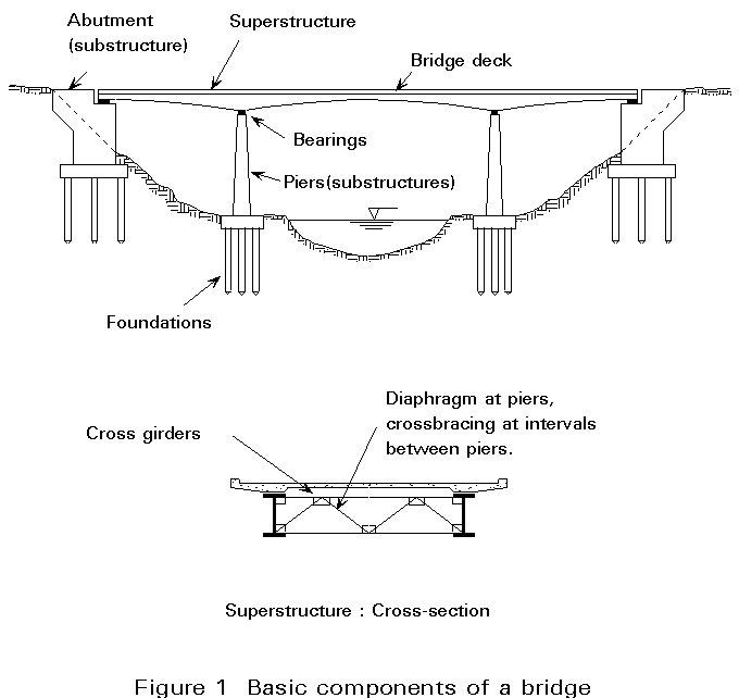
In Figure 1 the principal components of a bridge structure are shown.
The two basic parts are:
The former includes the piers, the abutments and the foundations.
The latter consists of the deck structure itself, which support the direct loads due to traffic and all the other permanent and variable leads to which the structure is subjected.
The connection between the substructure and the superstructure is usually made through bearings. However, rigid connections between the piers (and sometimes the abutments) may be adopted, particularly in frame bridges with tall (flexible) piers.
Piers may be made of steel or concrete. Even in steel and composite bridges, reinforced concrete piers are very often adopted. In some cases, e.g. very tall piers or those made by precast concrete segments, prestressed concrete may be adopted. Piers are of two basic types:
Concrete column piers may have a solid cross-section, or a box section may be the shape chosen for the cross-section (Figure 2) for structural and aesthetic reasons.
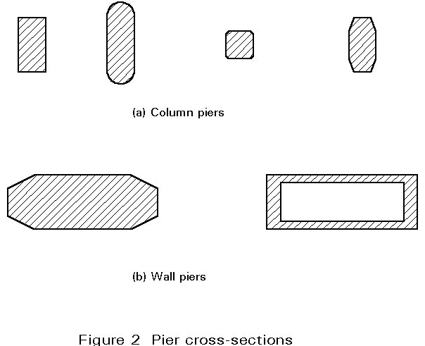
Wall piers are generally less economical and less pleasing from an aesthetic point of view. They are very often adopted in cases where particular conditions exist, e.g. piers in rivers with significant hydrodynamic actions or in bridges with tall piers where box sections are adopted.
Piers may be of constant cross-section or variable cross-section. The former solution is usually adopted in short or medium piers and the latter in tall piers where at least one of the cross-section dimensions varies along the length of the pier.
The abutments establish the connection between the bridge superstructure and the embankments. They are designed to support the loads due to the superstructure which are transmitted through the bearings and to the pressures of the soil contained by the abutment.
The abutments must include expansion joints, to accommodate the displacements of the deck, i.e. the longitudinal shortening and expansion movements of the deck due to temperature.
Two basic types of abutments may be considered:
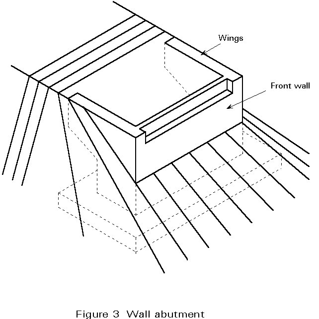
Counterfort wall abutments (Figure 3 and 4) are adopted only when the topographic conditions and the shapes of the earthfill are such that an open abutment (Figure 5) cannot be used. They are generally adopted when the required height of the front wall is above 5,0 to 8,0m (Figure 4). If the depth is below this order of magnitude, counterfort walls may not be necessary and a simple wall cantilevering from the foundation may be adopted.
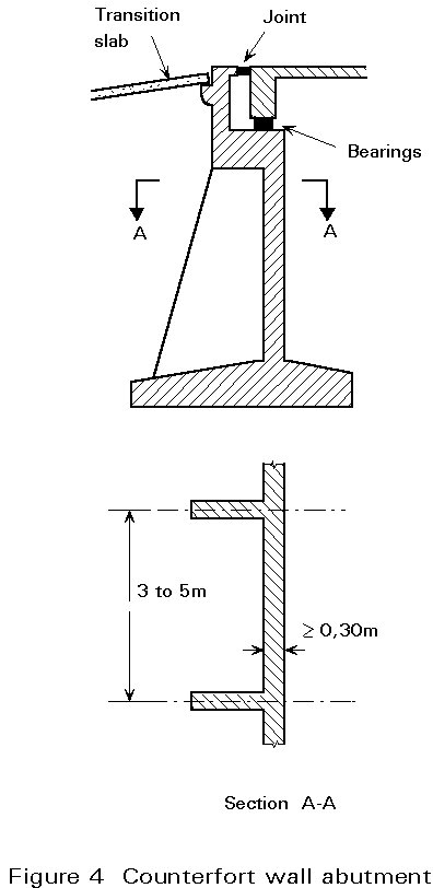
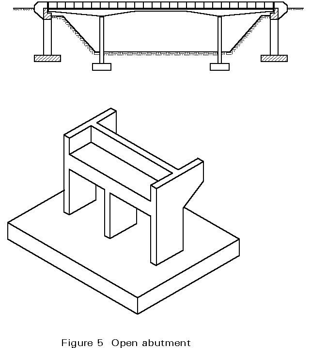
The connection between the abutments and the earthfill may include a transition slab (Figure 4) which ensures a smooth surface of the pavement even after settlement of the adjacent earthfill.
It is common in bridge terminology to distinguish between:
It should be understood that bridge structures are basically three-dimensional systems which are only split into these two basic systems for the sake of understanding their behaviour and simplifying structural analysis.
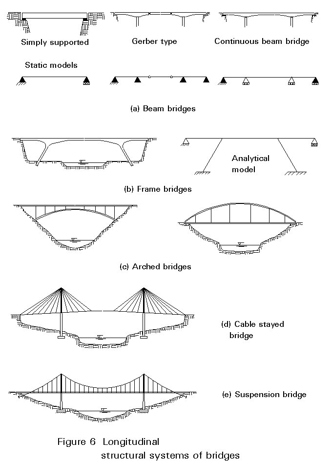
The longitudinal structural system of a bridge may be one of the following types which are illustrated in Figure 6:
The types of girder incorporated in all these types of bridges may either be continuous i.e. rolled sections, plate girders or box girders, or discontinuous i.e. trusses.
Beam bridges are the most common and the simplest type of bridge (Figure 6a), whether they use statically determinate beams (simply supported or Gerber beams) or continuous beams. Simply supported beams are usually adopted only for very small spans (up to 25m). Continuous beams are one of the most common types of bridge. Spans may vary from small (10 - 20m) to medium (20 - 50m) or large spans (> 100m). In medium and large spans continuous beams with variable depth section are very often adopted for reasons of structural behaviour, economy and aesthetics (Figure 1).
Frame bridges are one of the possible alternatives to continuous beams (Figure 6b). Avoiding bearings and providing a good structural system to support horizontal longitudinal actions, e.g. earthquakes, frames have been adopted in modern bridge technology in prestressed concrete bridges or in steel and composite bridges. Frames may be adopted with vertical piers (the most common type) or with inclined struts (Figure 6b).
Arches have played an important role in the history of bridges. Several outstanding examples have been built ranging from masonry arches built by the Romans to modern prestressed concrete or steel arches with spans reaching the order of 300m.
The arch may work from below the deck, from above the deck or be intermediate to the deck level (Figure 6c). The most convenient solution is basically dependent on the topography of the bridge site. In rocky gorges and good geotechnical conditions for the springings, an arch bridge of the type represented in Figure 6(c) is usually an appropriate solution both from the structural and aesthetic point of view.
Arches work basically as a structure under compressive stress. The shape is chosen in order to minimise bending moments under permanent loads. The resultant force of the normal stresses at each cross-section, must remain within the central core of the cross-section in order to avoid tensile stresses in the arch. Arches are ideal structures to build in materials which are strong in compression but weak in tension, e.g. concrete.
The ideal "inverted arch" in its simplest form is a cable. Cables are adopted as principal structural elements in suspension bridges where the main cable supports permanent and imposed loads on the deck (Figure 6(e)).
Good support conditions are required to resist the anchorage forces of the cable. In the last few years, a simpler form of cable bridges has been used - the cable stayed bridge.
Cable stayed bridges (Figure 6(d)) have been used for a range of spans, generally between 100m and 500m, where the suspension bridge is not an economical solution. The range of spans for cable stayed bridges is quite different from the usual range of spans for suspension bridges - from 500m to 1500m. Cable stayed bridges may be used with a deck made in concrete or in steel. Generally, cable stayed bridges are designed with very slender decks which are "continuously" supported by the stays which are made of a number of strands of high strength steel.
Three main types of transverse structural system may be considered:
Slab cross-sections are only adopted for small spans, generally below 25m, or where multiple girders are used for the longitudinal structural system, at spacings of 3 - 4,5m. Beam-slab cross-sections (Figure 1) are generally adopted for medium spans below 80m where only two longitudinal girders are provided. For large spans (> 100m), and also for some medium spans (40 - 80m), box girder sections are very convenient solutions leading to good structural behaviour and aesthetically pleasing bridge structures. Box girders are used in prestressed concrete or in steel or composite bridges.
During the industrial revolution of 19th century steel products became more competitive and structural steel began to be adopted for bridge construction. From then on, large truss bridges and suspension bridges where developed. Unfortunately this development was accompanied by several accidents, e.g. the railway bridge over the Tay [1] in 1879 and the Quebec bridge in 1907. The former was rebuilt (1890) with spans of 521m; the Quebec bridge was only rebuilt in 1917.
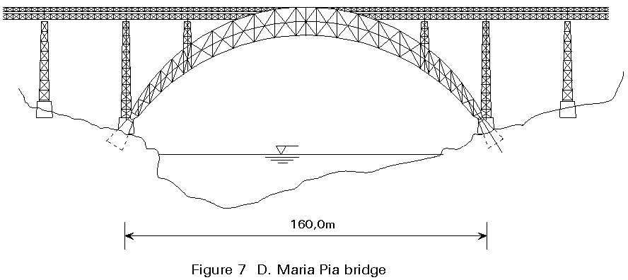
Truss girders or arches built by truss systems have been widely adopted. An example of an arch-truss bridge designed by G Eiffel (the designer of the famous Paris tower) is presented in Figure 7. This bridge, built in 1868 in Oporto over the Douro River, Portugal, has a central span of 160m.
It is interesting to note that one of the commonest types of modern steel bridge - the box girder bridge was first introduced in bridge engineering in 1846 by Stephenson with the "Britannia Bridge" (a cast iron 142m span box girder bridge), yet was only fully developed after the Second World War. The knowledge of aeronautical engineering of thin-walled structures was used. Between 1969 and 1971 several accidents occurred to box girder bridges, e.g. Vienna bridge over the Danube (1969), Milford Haven bridge in the United Kingdom (1970), Melbourne bridge in Australia (1970) and Coblenz bridge in Germany (1971). As a result a large research effort was made over the last two decades to investigate the basic structural element of these bridges - the stiffened plate. The behaviour of stiffened plates is now sufficiently known for safe large box girder bridges to be designed in steel. Special consideration during erection and execution phases is given to all aspects of structural stability.
Three basic types of structural elements are adopted for steel bridge superstructures:
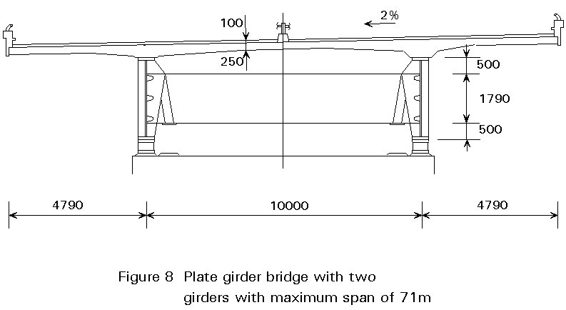
Plate girder bridges with only two girders, even for very wide decks (Figure 8), are very often preferred for the sake of simplicity [2]. However, in bridge construction, a classical solution consists in adopting several I beams (hot rolled sections for small spans - up to 25m) with 3,0 to 4,5m spacing. Diaphragms may be provided between the beams (transverse beams) to contribute to transverse load distribution and also to lateral bracing. The top flanges of the beams have continuous lateral support against buckling provided by the deck.
There are two basic solutions for the deck [3] - a reinforced concrete or partially prestressed concrete slab and an orthotropic steel plate (Figure 9). In the former the slab may act independently of the girders (a very uneconomic solution for medium and large spans) or it may work together with the girders (composite bridge deck). The composite action requires the shear flow between the slab and the girders to be taken by shear connectors.
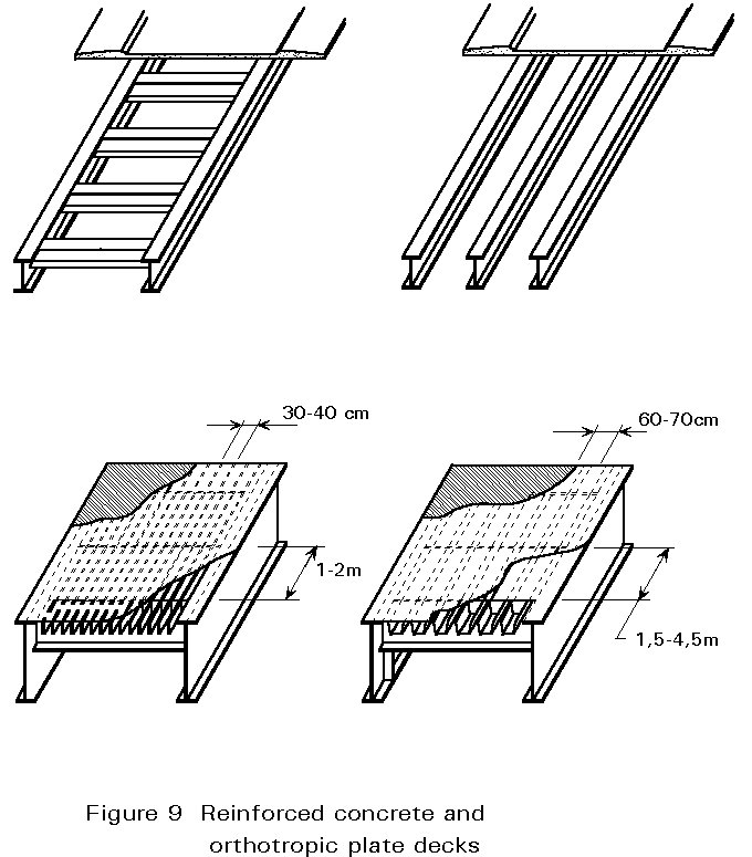
Concrete decks are usually more economic than orthotropic steel plates. The latter are only adopted when deck weight is an important component of loading, i.e. for long span and moveable bridges.
The orthotropic plate deck, acting as the top flange of the main girders, gives a very efficient section in bending. The deck is basically a steel plate overlain with a wearing surface which may be concrete or mastic asphalt. The steel plate is longitudinally stiffened by ribs which may be of open or closed section. Transversally, the ribs are connected through the transverse beams (Figure 9) yielding a complex grillage system where the main girders, the steel plate, the ribs and the floor beams act together.
Top flanges of box girders, e.g. in Niteroi bridge (Figure 10) with a 300m span [4] (the largest in the world for a box girder bridge) or in the deck of cable stayed bridges (Figure 11) [5] or suspension bridges like the Humber bridge (Figure 12) with a lightweight wearing surface give a deck of very low dead load which makes this type of solution very suitable for long spans [4,8]. The biggest disadvantage of orthotropic steel plate decks is their initial cost and the maintenance required when compared to a simple concrete slab. However, for box girders the maintenance cost may be lower than for an open orthotropic deck.
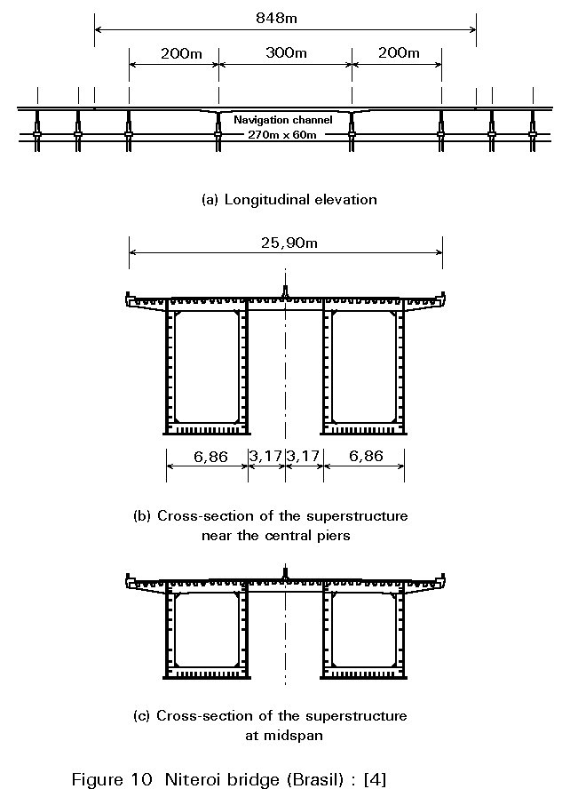
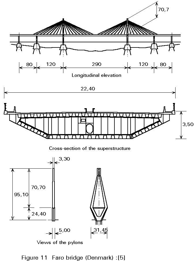
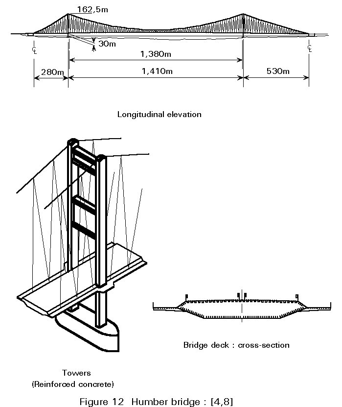
Plate girder bridges can provide a very competitive solution for short and medium span bridges. They are almost always designed to act compositely with the concrete slab.
The plate girders are fabricated with two flanges welded to a thin web which usually has transverse stiffening and may have longitudinal stiffening.
Three types fo bridge cross-section may be used. For shorter spans, up to 60m, multiple girders at spacings of 3 to 4,5 m enable a simple reinforced concrete slab to be used, as shown in Figure 13(a).
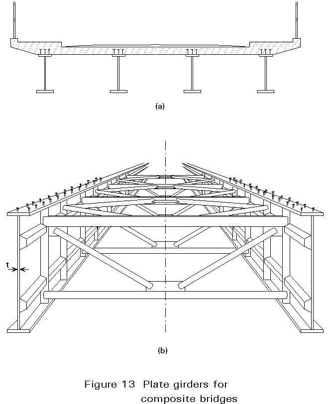
For medium spans (50 to 100 m) it is usually more economic to use only two plate girders, Figure 13(b). A prestressed concrete slab, usually of varying depth, may be used that sits directly on the two girders.
Alternatively cross girders may be adopted with twin longitudinal girders that support the slabs at 3 to 4,5 m centres.
The complexity of fabrication of the plate girder is primarily controlled by the web slenderness (depth/thickness ratio). For short spans a low slenderness is feasible with a web that is unstiffened except at cross bearing positions and supports. For medium spans the web will usually need to be of intermediate slenderness and require vertical (transverse) stiffening. For larger spans the web is likely to require both transverse and longitudinal stiffening, as shown in Figure 13(b).
The distance between transverse stiffeners is of the order of magnitude of the depth of the girder. Where they are required, 1 to 3 longitudinal stiffeners are usually provided.
In sections at supports, it is essential to adopt vertical stiffeners to resist the high reaction forces.
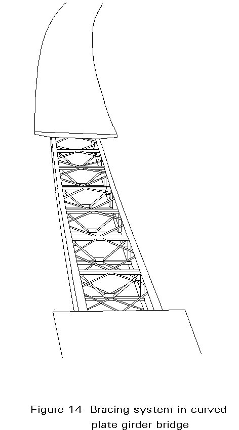
One of the basic requirements when designing plate girder bridges is the bracing system (Figure 13b and 14), which is required for all but the simplest structures. The bracing:
The bracing system generally includes:
The former (Figure 14) consists of a set of crossing diagonal members and is located near the bottom or near the top and the bottom flanges; the bridge deck may act as a horizontal bracing.
The latter are a set of bracings (trusses) normal to the bridge axis - Figure 13 - which provide resistance to the deformation of the overall cross-sections of the bridge.
In modern bridge construction several simplifications have been tried in order to reduce, as much as possible, the complexity of the bracing systems. In some cases, the horizontal bracing system located near the bottom flanges has been eliminated. The ultimate simplification consists in avoiding the intermediate cross frames completely. This is only possible if the lateral stability of the girders is guaranteed and the horizontal forces are taken by other elements of the superstructure.
A truss girder may be adopted in some cases as an alternative to a plate girder. Although less commonly used in modern construction because of their high fabrication content, they may still be an economic solution for large spans, say between 100 and 200 metres.
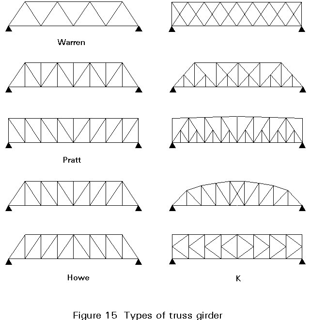
A plane truss girder may be considered as a deep beam where the flanges are the compression and tension chords of the truss and the web of the beam is replaced by an open triangular system which resists the shear forces.
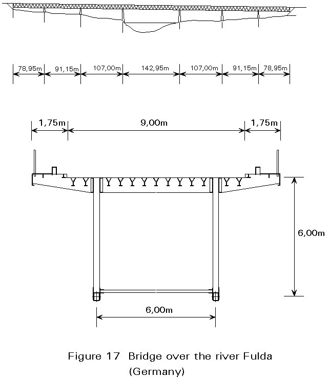
Several types of truss girders are used in bridge design. Some typical examples are shown in Figure 15. Truss girders may be adopted in simply supported (Figure 15) or continuous spans (Figure 16 and 17).
Bracing systems are required in truss girder bridges, since truss girders can only resist forces in their planes.
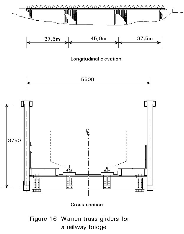
Truss girders working from above the deck (Figure 16) have been extensively used in railway bridges, even for medium spans of the order of 40 to 100 metres [6].
From an aesthetic point of view, it is important to reduce as far as possible the number of bar elements in the truss girder. If possible the simplest triangular system (Warren type) yields the best appearance when the bridge is viewed from skew angles (Figure 16).
Truss chords and diagonals are made using hot rolled sections generally of an open shape for simplicity of connections. However, tubular cross-sections may be adopted, for example, for the chords.
An example is shown in Figure 17 which represents the bridge over the river Fulda in Germany, near Kassel [7]. In this bridge, a Warren type truss was used with a maximum span/depth ratio of 23,8. The deck is an orthotropic plate giving a reduced dead weight for the superstructure.
For long spans (say, in excess of 100m) box girders are, in general, the most common and efficient type of bridge superstructure. Built with an orthotropic plate deck to reduce the dead weight of the bridge, or with a concrete slab to obtain a composite cross-section, box girders have many structural advantages when compared to plate girders and truss girders. Some of the advantages are:
Due to the high torsional rigidity of this type of cross-section, box girders are a very convenient solution for bridges curved in plan.
For large spans, the depth of continuous box girder bridges may vary along the span giving improved structural efficiency to accommodate the large bending moment at the supports (Figure 10).
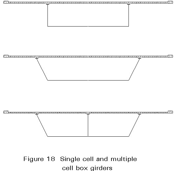
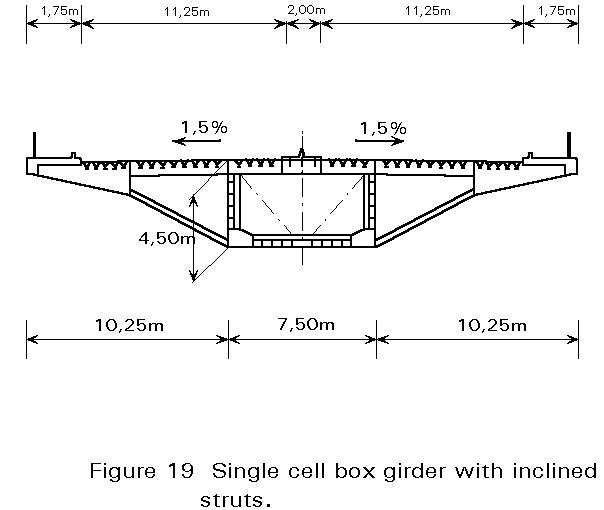
The cross-section may consist of a single cell box, with vertical or inclined webs, or of a multiple cell box (Figure 18). Other possibilities consist of using, for example, a single cell with inclined struts to support large overhangs (Figure 19).
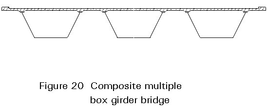
For medium spans, a type of box girder deck very common in bridge construction, e.g. in North America, is the composite box girder deck made of several parallel boxes interconnected by a reinforced concrete slab deck (Figure 20). Composite action between the box girders and the reinforced concrete slab is obtained through shear connectors.
The two flanges associated with each web in composite box girder bridges may be quite narrow because they only need to transfer the load to the web and to accommodate the shear connectors. A minimum flange width may therefore be defined by edge distances and clearances for automatic welding of shear connectors.
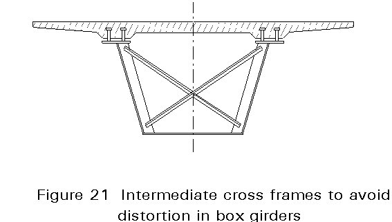
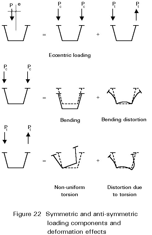
Load bearing diaphragms are necessary at supports to transfer the reaction forces. In addition, even in small box girders, it is good practice to adopt intermediate cross frames (say, at 10m to 15m apart) to avoid distortion of the cross-section under eccentric loading (Figure 21). It should be noted that during construction some "box" girders have open sections and so will be subjected to distortion under eccentric loading. Figure 22 summarises the distortions that can occur in open topped boxes during construction. A top bracing between the top flanges and/or a cross diagonal bracing between the webs is generally convenient to overcome the distortion effects during execution. The diagonal bracing may consist of small size angles welded to plate stiffeners.
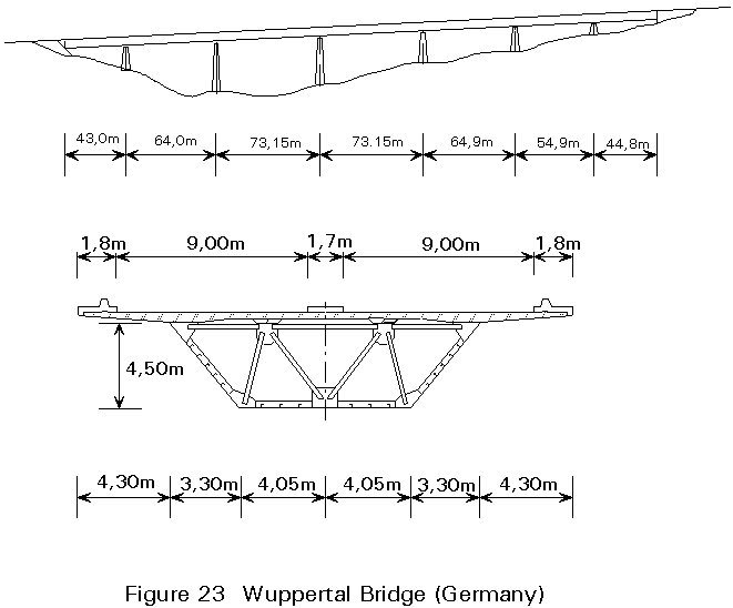
The use of composite box girders in wide bridges with long spans is possible with single cell boxes. Internal cross trusses may be used, not only to maintain the shape of the cross-section (avoiding distortion) but also to support longitudinal stringers for the reinforced concrete slab. A solution of this type is shown in Figure 23 [7].
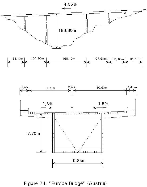
For long spans an orthotropic plate deck is preferred to reduce the dead load of box girder bridges. A solution with a rectangular box girder bridge with a main span of 200m is given in Figure 24 which shows the "Europe Bridge" in Austria [7].
The use of box girders is not restricted to beam bridges. Slender box girders in cable stayed bridges have been used with orthotropic plate decks (Figure 11). Although, in the last few years, concrete box girder decks have been shown to be an economic solution for some cable stayed bridges, steel box girders are the most convenient solution for long spans. Compared to open sections, box girder decks in cable stayed bridges present a significant advantage in respect of aerodynamic stability. The advantage is associated with a higher natural frequency of torsional vibration of the deck avoiding an interaction with the fundamental mode corresponding to vertical vibrations (flexure mode). The risk of flutter instabilities is thus eliminated.
For reasons similar to those given for cable stayed bridges, slender steel box girders with orthotropic plate decks have been adopted in modern suspension bridges.
The cross-section of the Humber bridge, where a steel box girder was adopted weighing only 2,6 kN/m2 is shown in Figure 12. The same aerodynamic advantages pointed out for box girder decks of cable stayed bridges, are valid for suspension bridges.
[1] Wittfoht, H., Triumph der Spannweiten, (Spanish ed. - Puentes - Ejemplos Internacionales) Ed. Gustavo Gili, Barcelona, 1975.
[2] Vevey, Bulletin Technique, 1978.
[3] Alvarez, R., La estructura metalica hoy, Libreria Tecnica Bellisco, 1975.
[4] Pfeil, W., "Pontes" Ed. Campus Ltd, Rio de Janeiro, 1983.
[5] Walther, R., Ponts Haubanés, Presses Polytechniques Romandes, 1985.
[6] Reis, A. and Abecasis, T., Railway Bridge over the River Zezere, preliminary Design Report, Grid Consulting Engineers, 1990.
[7] O'Connor, C., Design of Bridge Superstructures, John Wiley & Sons, 1971.
[8] Gimsing, Niels, Cable Supported Bridges, John Wiley & Sons, 1983.
Note: A general list of wider reading is given at the end of Lecture 1B.6.2.