ESDEP WG 2
APPLIED METALLURGY
Presentation of the most recent steelmaking and rolling technologies.
Lecture 2.1: Characteristics of Iron-Carbon Alloys
Lecture 2.3.1: Introduction to Engineering Properties of Steels
Lecture 2.3.2: Advanced Engineering Properties of Steels
Lecture 2.5: Selection of Steel Quality
Lecture 2.6: Weldability of Structural Steels
The blast furnace process, the oxygen steelmaking process and the electric arc furnace process are described. Ladle steelmaking and casting technologies are also introduced.
Finally, the different rolling processes and rolling conditions are presented, as well as the usual heat treatments.
Steelmaking technology has greatly changed during the last two decades under the pressure of increased demand, new specifications and the need to reduce energy and material consumption. Production efficiency has been improved by increasing the melt capacity of furnaces, implementing on-line computer control modules, and introducing new technologies, such as the combined blowing process for LD (Linz Donawitz) converters, the Ultra High Power (UHP) electric furnace, the ladle steelmaking processes and continuous casting.
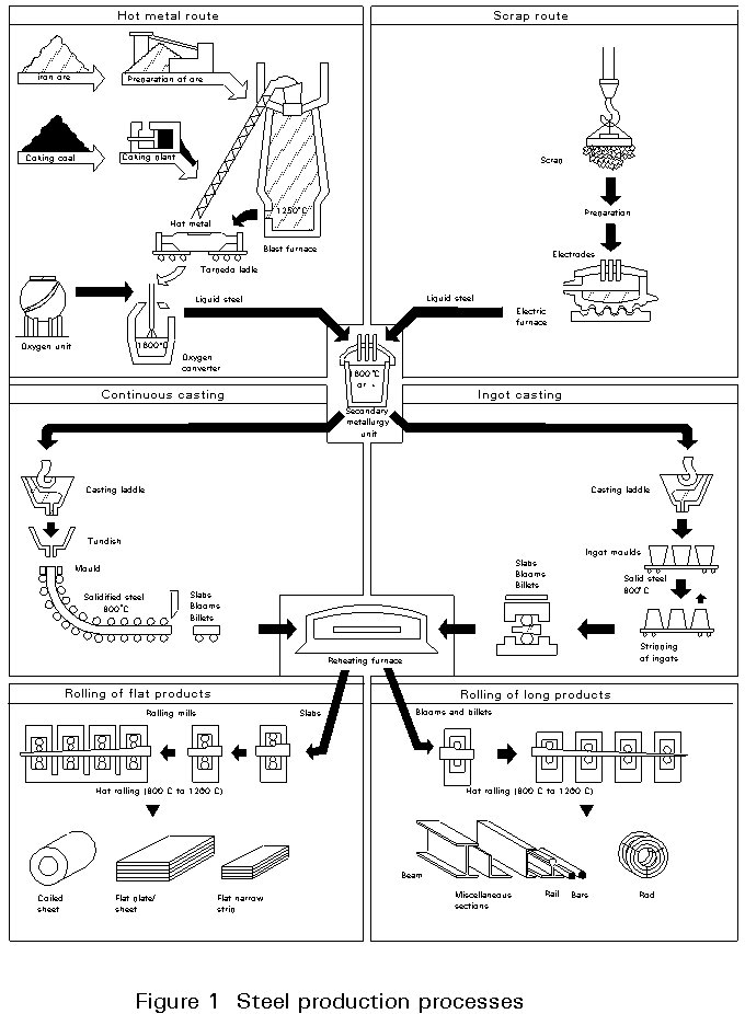
Steel is produced by two process routes (Figure 1):
In both routes the process consists of producing refined iron to which is added the required alloying elements to produce the finished steel specification.
Their respective shares in crude steel production are 70% (BOF) and 30% (EAF). High production rates and low impurity steel production give a dominant role to the first process route. Low energy costs and an ample supply of recycled scrap ensure a competitive market share for the second process route, especially when using the UHP furnace.
Before casting, the steel can be refined in the ladle by various processes according to the specification with respect to its deoxidation state, inclusion content and level of phosphorus, sulphur, nitrogen and hydrogen. At the same time, its content of carbon, manganese and microalloying elements such as niobium, vanadium and titanium can be adjusted. This process step is generally referred to as Secondary or Ladle steelmaking.
During the last step of steelmaking, the steel is cast either into slabs, blooms or billets on a continuous casting machine or into ingots, depending on the final product. Flat products and light shapes are normally produced from continuous cast feedstock; whereas heavy beams and plates are more likely to follow the ingot route.
Sintered iron ores are reduced to raw iron in the blast-furnace. The raw iron is then transformed into crude steel in the oxygen converter. As this operation yields energy, additional scrap is introduced in order to control temperature.
Sinter plant
The iron feedstock of the blast furnace is the sinter, which is produced in the sinter plant. In the sinter process, a mix of iron ore fines, lime and coke (almost pure carbon) is charged in a 45 cm thick layer onto a moving conveyor (Dwight Lloyd process) and partially melted to form a porous mixture of iron oxides and gangue. Coke consumption is about 50 kg/t sinter product.
Blast furnace process (Figure 2)
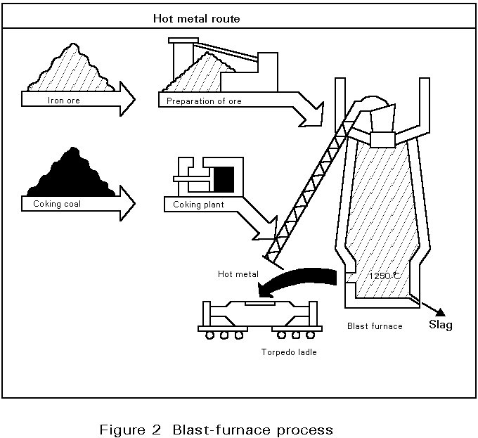
The blast-furnace is a shaft type furnace operating by the counterflow technique: the descending burden of sinter and coke, charged from the top of the furnace, is heated and reduced by the combustion gases ascending from the tuyere zone where a hot air blast is injected to burn C to CO. The air blast is compressed by a blower and heated in special stoves to 1100°C by combustion of the cleaned furnace exhaust gases.
The iron oxides (FeO, Fe2O3) and some of the elements present in the gangue of the sinter are reduced by CO gases to produce hot metal.
The blast furnace flue dust containing about 40% Fe is recycled by the sinter process.
The high permeability of the sinter and the even distribution of the charge produced by revolving chutes help to improve productivity of the blast furnace. Coke consumption can be reduced to 470 kg/t of hot metal. The use of tuyere injectant such as powdered fuel (120 kg/t) or oil (60 kg/t) further reduces the coke consumption of the furnace and so the cost.
Below the tuyere zone, where the temperature is highest, the molten material collects on the furnace hearth where the liquid iron (pig iron) separates from the slag by difference in density. The slag and liquid pig iron are tapped from separate tapholes. The tapped slag is granulated by water jets and removed for use in other products including road construction materials, fertilizers, etc. The liquid pig iron (hot metal) is tapped into ladles or torpedo cars (capacity: 300 - 400 t) and conveyed to the steel plant for refinement and conversion into steel.
A typical analysis of the hot metal produced at a temperature of 1400°C is:
4,7% carbon (C); 0,5% manganese (Mn); 0,4% silicon (Si); 0,1% phosphorus (P) and 0,04 % sulphur (S), the remainder being iron (Fe).
Sulphur removal from the melt needs low oxygen activities. Desulphurization is therefore achieved in the hot metal by injection of calcium carbide fluxes to form calcium sulphide (CaS) or fluxes containing metallic magnesium to form MgS and CaS.
The oxygen steelmaking process (Figure 3)
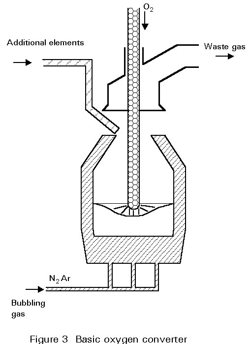
The basic oxygen furnace or LD converter (originating from the Linz-Donawitz process started in 1956) is based on oxygen injection by a lance into the melt of hot metal. Scrap and lime are charged into the converter to cool the melt and remove phosphorus, silicon and manganese.
The converter is lined with dolomite or magnesite refractory which best resists erosion by slag and heat during oxygen blowing. The life of a converter lining is about 800 to 1400 heats.
The oxygen burns out the carbon as carbon monoxide CO and carbon dioxide CO2 gas which is collected in the chimney stack and cleaned of its dust (Fe203, and lime particles, etc.). The elements Mn, Si and P are oxidized and combine with lime (CaO) and FeO formed by the oxidation of Fe to form a molten slag.
As these oxidation reactions are highly exothermic, the process needs cooling in order to control the temperature of the melt. This cooling is done by charging scrap (recycled plant and mill scrap) and by adding iron ore during the blowing process.
The oxygen blowing takes 15 to 20 minutes, regardless of the size of the converter (70 to 400 t) because the oxygen flow rate of the lance is adjusted to the melt weight. The charging and discharging of steel and slag, including sampling for temperature and analysis of the melt, extends the tap to tap time of a converter to 40 - 60 minutes. The process is characterized by high productivity and steel of low impurity content.
The steel is tapped to the ladle through a taphole by tilting the furnace. During this operation ferro-alloys for control of the steel composition are added to the ladle. The oxidized slag containing 12 to 16% of Fe is poured into a cast iron slag pot after the tapping and is disposed of in a slag yard.
A major development in the oxygen lance blowing technique, known as Lance Bubbling Equilibrium (LBE) was developed in the mid-seventies and has been widely adopted. Neutral gas, typically argon, is injected through permeable elements in the bottom of the converter, stirring the melt and slag. This significantly increases metallurgical efficiency (lower Fe losses and lower P content), productivity, and the heat and mass-balance of the process (cost reduction).
Technology
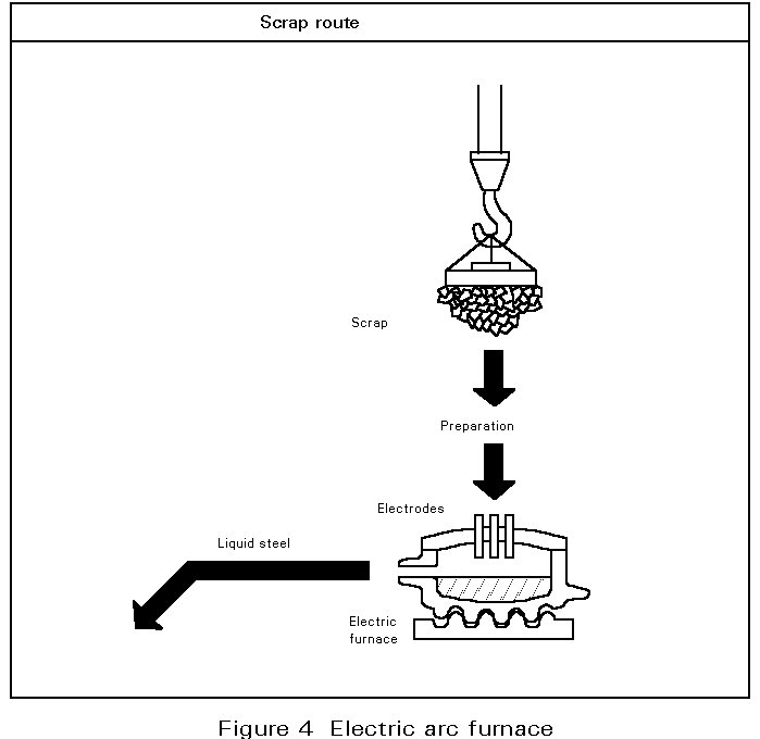
In the electric arc furnace process, the cold metallic charge, mainly scrap, is melted by the energy of electric arcs generated between the tips of graphite electrodes and the conductive metallic charge.
The three electrodes and the furnace roof are raised and swung away from the furnace shell to allow the charging of scrap. The electrodes maintain the arc in accordance with the voltage and current level selected to produce the desired power input at the desired arc length for melting and refining. As the noise generated by the arcs is high during the melt-in-period, with levels up to 120 dBA, special protection is provided to the operators cabin and the furnace has a special enclosure.
The three phase alternating current is supplied by the low voltage side (300 - 700V) of a high power transformer. The nominal transformer rating, expressed as KVA/t, extends from 300 to 500 KVA/t for high power furnaces and from 500 KVA/t upwards for Ultra High Power (UHP) furnaces. These furnaces have an inner diameter of 6 to 9 metres with a capacity of 100 to 200 tons of steel. The tap-to-tap time for these furnaces is 90 to 110 minutes.
The traditional role of the EAF process is producing alloy, tool and carbon steels, and it has been extended by the UHP furnace to mass steel production. Thus, the concept of the Mini-Mill was born. As the size and productivity of the furnace increased, the operation of continuous casting for billet and bloom production became possible. Flat products specification, however, require low residual impurity levels and even higher production rates which cannot be satisfied by the UHP-furnace.
The share of steel production produced by electric arc furnace is about 30%, at which level it seems to be stabilized as scrap of acceptable quality becomes more scarce. Pellets and sponge iron of higher price have to be used for critical steel grades to control the level of injurious elements, i.e. copper, nickel, tin, etc..
Metallurgy
The traditional high power furnace produces high quality carbon and alloy steels by the two slag technique. After melt down of the scrap charge, a first oxidizing slag removes the elements P and Si and reduces carbon to the required level. After deslagging, a second basic reducing slag is formed to lower the sulphur and oxygen contents and the steel composition is adjusted by ferro alloy additions.
The UHP furnace operates with only a lime based oxidizing slag. The melt down of the scrap charge is accelerated by the use of oxy-fuel burners positioned to reach the cold spots of the large hearth furnace. Oxygen lancing and carbon additions are used to make a foaming slag which yields better energy input from the arcs and improves dephosphorization. After this period, the melt is discharged by a taphole. Deoxidation and refining under reducing slag takes place in the steel ladle (secondary steelmaking). The 100% scrap charge makes the process more vulnerable to injurious "tramp elements", such as copper, nickel and tin which cannot be removed by the process, their stability being higher than that of iron. To control these "tramp elements", it is of great importance to identify the sources of the incoming scrap and to make provision to keep the different qualities separate.
Achieving the required properties of steel often requires a high degree of control over carbon, phosphorus, sulphur, nitrogen, hydrogen and oxygen contents. Individually or in combination, these elements mainly determine material properties such as formability, strength, toughness, weldability, and corrosion behaviour.
There are limits to the metallurgical treatments that can be given to molten metal in high performance melting units, such as converters or electric arc furnaces. The nitrogen and phosphorus content can be reduced to low levels in the converter but very low carbon, sulphur, oxygen and hydrogen contents (< 2 ppm) can only be obtained by subsequent ladle treatment. To ensure appropriate conditioning of steel before the casting process, the alloying of steel to target analysis and special refining treatments are carried out at the ladle metallurgy stand.
The objectives of ladle steelmaking can be summarized as follows:
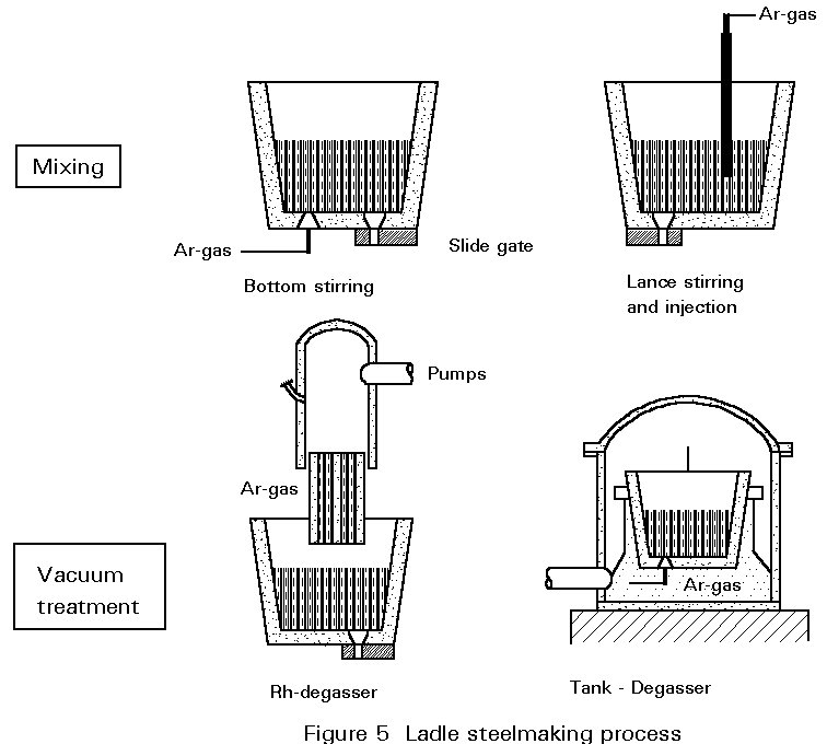
The high oxygen content of the converter steel would result in large blow-hole formation during solidification. Removal of the excess oxygen ("killing") is therefore vital before subsequent casting of the steel. Steels treated in this way are described as killed steels. All secondary steelmaking processes allow deoxidising agents to be added to the ladle so that deoxidation in the converter vessel is not necessary.
Deoxidation can be performed by the following elements classified by increasing deoxidation capacity; carbon - manganese - silicon - aluminium - titanium. The most popular are silicon and aluminium.
After addition, time must be allowed for the reaction to occur and for homogeneity to be achieved before determination of the final oxygen content using EMF probes (electro-chemical probe for soluble oxygen content).
As most of these deoxidation agents form insoluble oxides, which would result in detrimental inclusions in the solid steel, they have to be removed by one of the following processes during the subsequent refining stage:
× homogeneous steel composition and temperature
× removal of deoxidation products
× desulphurization of aluminium-killed steel grades
× sulphide inclusion shape control.
Stirring of the melt by argon or by an inductive stirring equipment and arc heating of the melt (low electric power, typical 200 KVA/t) allows:
× long treatment times
× high ferro-alloy additions
× high degree of removal of deoxidation products due to long treatment under optimized conditions
× homogeneous steel composition and temperature
× desulphurization, if vigorous stirring by argon.
In the RH process the steel is sucked from the ladle by gas injection into one leg of the vacuum chamber and the treated steel flows back to the ladle through the second leg. In the tank degasser process, the steel ladle is placed in a vacuum tank and the steel melt is vigorously stirred by argon injected through porous plugs in the bottom of the ladle.
Vacuum treatment achieves:
× reduction of the hydrogen content to less than 2 ppm
× considerable decarburization of steel to less than 30 ppm when oxygen is blown by a lance (RH - OB)
× alloying under vacuum
× homogeneous steel composition, high degree of cleanness from deoxidation products
High temperature losses (50 - 100°C) are a disadvantage, therefore high superheat of the melt prior to this process is essential.
For most secondary steelmaking techniques it is either desirable or essential to stir the liquid steel. Gentle stirring is sufficient for inclusion removal; non-metallic inclusions are brought into contact with liquid slag on top of the melt where they can be fixed. For degassing and desulphurization however, violent stirring is necessary to increase the surface of steel exposed to vacuum (H-removal) or to mix the steel and slag for good desulphurization efficiency.
For solidification, steel is cast into moulds either of cast iron for the ingot casting route or into copper moulds for the continuous casting process.
The heat of liquid steel is extracted by the cold mould surface so that crystals can form and grow. A solid shell is formed and solidification progresses by maintaining the cooling.
During solidification, the density of metals rises and causes shrinkage. This favours the stripping of the cast from the mould. However, this contraction also causes internal shrinkage which tends to leave a hollow core in the cast product. In continuous casting this is prevented by the continuous flow of molten metal to the mould. For ingot casting an adequate liquid metal pool has to be maintained at the head of the mould by the provision of exothermic material (hot-top).
A second concern during the solidification process is segregation due to the fact that some solute elements have a much lower solubility in the solid than in the liquid phase. The segregation tendency is most pronounced for sulphur, phosphorus, oxygen and hydrogen. As has been described, these elements can be controlled to sufficiently low levels by the metallurgical process steps. The manganese content of steel also combines with sulphur to form manganese sulphide inclusions which are elongated during rolling and become detrimental to steel properties if significant stresses are applied perpendicular to the rolling direction. For such applications, shape and content of the sulphide inclusions have to be controlled closely during the refining stage.
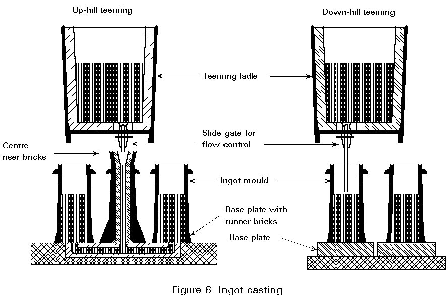
The casting of ingots is a discontinuous process in which the ingot moulds are filled individually by top pouring or in batches by a central feeder through runners in the base plate. This up-hill teeming technique is characterized by a low rising speed of the steel in the mould, which reduces cracks and surface defects when casting critical steel grades.
The teeming operation is done directly from the steel ladle through a sliding gate valve at the bottom that regulates the steel flow, and a nozzle that gives a concentric steel jet.
The ingot weights and sections are fixed by the capacity of the primary rolling mill. The ingot size may vary from 4 to 30 t, or even higher for forging.
The ingot remains in the mould until solidification is complete. Then the mould is stripped off by crane and left to cool in the mould yard. The ingot is charged into the soaking pit furnace to equalize and raise the temperature for the rolling process (» 1300°C).
The solidification of an ingot progresses from the bottom (cooled by the base plate and the mould) to the top of the ingot.
In the case of a fully killed (Si + Al) steel melt, with a low free oxygen content, the solidification shrinkage is concentrated at the upper centre of the ingot. To minimise the development of shrinkage porosity in this region, the top of the ingot is insulated (hot top) to provide a reservoir of liquid metal to fill up the hollow core. The hot top is subsequently cropped. This scrap amounts to approximately 12% of the ingot weight.
By deoxidation with silicon alone, the free oxygen content of the melt can be set to a well defined level so that towards the end of solidification it will react with the carbon of the melt to form CO gas. The formation of these small gas bubbles, or blow holes, compensates for the shrinkage of steel and top crop losses are small (» 2%). The blow-holes are eliminated during primary rolling. Such steels are referred to as 'balanced' steels.
Ingot casting is very flexible as regards product specifications and the production of small orders on relatively short delivery terms. It is also indispensable for the forming of heavy shaped profiles like beams, heavy plate or heavy forging pieces.
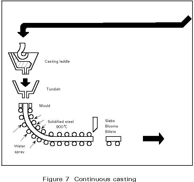
The continuous casting process has become the major casting technology for steel plants. The reasons are:
The ratio of continuous cast steel has reached 80 - 90% of total raw steel production in the Western World. The advent and rapid growth of mini-mills could not have occurred without continuous billet casting technology.
The essential feature of the continuous casting process is the oscillating water-cooled copper mould. The main function of this mould is to form a solidified steel shell having sufficient strength to prevent breakouts below the mould. This is achieved by the high heat extraction in the mould system. The mould walls are tapered to accommodate the strand shrinkage over the mould length of 700 mm and to maintain a high heat flux.
The oscillation creates a relative movement between strand and mould, and prevents metal sticking to the mould surface. Stripping is facilitated by providing an adequate lubricant (casting powders or oil) at the steel meniscus. This lubricant is also essential to maintain a high heat extraction and prevent breakouts.
On leaving the mould, the strand is cooled by water sprays and is supported by rolls to prevent bulging until solidification is complete. Strand sections cover the range of semi-finished products, such as billets, blooms or slabs, for the hot finishing mills. Depending on the section to be cast, a continuous caster is laid out with two (slab), four (bloom or round caster) or six strands (for billets below 180 mm2 in size).
Modern casters are curved type machines which are cheaper and easier to accommodate in the plant than the original vertical machines. The curved strand is straightened by rollers after complete solidification and cut to the required length for further processing in the rolling mills.
Continuous casting technology makes the process continuous so that a number of molten steel batches are cast in sequence. To achieve a continuous supply of steel to the mould, the steel in the ladle is first cast into a tundish which acts as a reservoir during ladle changing and distributes the steel to the different moulds of the machine. Tundishes are equipped with stoppers or sliding gates to regulate the flow rate to the casting speed of the strand. To prevent oxidation by air exposure, the ladle and tundish streams are shrouded by refactory tubes.
There are various methods of forming steel into finished products, including hot forging, hot and cold rolling, seamless tube making and welded tube making. The most widely used process is hot rolling, which accounts for over 90% of all steel production.
Hot rolling involves reheating of ingots, slabs, blooms or billets to the region of 1200 - 1300°C and passing the material between two rolls (Figure 8). The piece of steel may be passed repeatedly back and forth through the same rolls with the roll gap being reduced progressively.
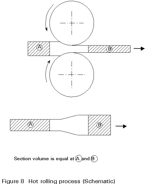
This operation is done in the hot state because the yield strength of steel decreases as temperature rises. Large deformations can thus be obtained with modest roll forces. It is necessary to control both the total reduction, which defines the degree to which the steel is worked, and the reduction in each pass in order to avoid excessive deformation leading to metal cracking or breakage.
The number of passes depends upon the input material and the size of the finished product; it can be as high as 70 before the material becomes too cold to roll down further. Plain barrel rolls are used for flat products such as plate, strip and sheet, while grooved rolls are used for structural sections, rails, rounds, squares, beams, sheet piles, etc.
The basic rolling unit is called a stand and consists of the rolls and a support structure (housing). The rolling mill comprises the stand or group of stands, complete with auxiliary facilities for control and regulation, such as roll drive motors, roller tables for entering and removing the metal, shears, scarfers, etc.
The simplest type of mill consists of a two-high stand. Generally, the two rolls can turn in both directions, which permits reversible operation such that the hot metal is passed repeatedly through the mill in opposite directions achieving progressive reduction in thickness.
When large reductions are required, four-high stands are used to achieve the required high roll forces. The cylindrical work rolls, through which the hot metal passes, are of relatively small diameter and are supported above and below by a second set of larger diameter backing rolls that transmit the force to the work rolls. A four-high stand may also be reversible.
The reduction in thickness of the hot material results in both length increase and sideways spread. The spreading, which depends mainly upon the amount of reduction, temperature, and roll diameter, must be controlled to give the correct dimensions and cross-section. Universal Mills have a set of vertical rolls at the delivery side of the horizontal rolls. In parallel face beam mills, they serve to provide a good dimensional finish to the final product and, in flat product mills, to edge the plates, improving finish and mechanical characteristics.
In addition to its function of shaping the steel into the required size, hot rolling improves the mechanical properties. Correct control of the cast steel chemical composition, final rolling temperature and amount of material reduction is necessary to give products the required physical properties. For certain steel qualities (e.g. high strength with good impact properties at low temperatures) "controlled rolling" or the QST process of quenching and self-tempering of the material during rolling is employed. This process involves either delaying or cooling until a specified lower temperature is reached before the final passes through the mill.
The main product routes for structural steel grades are summarized in Figure 9.
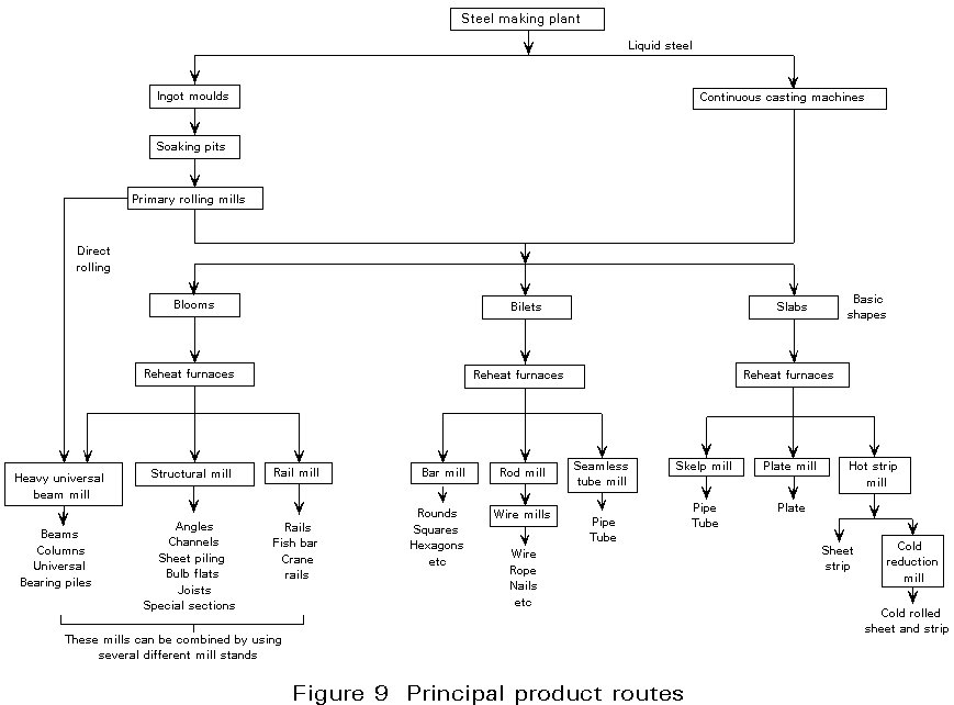
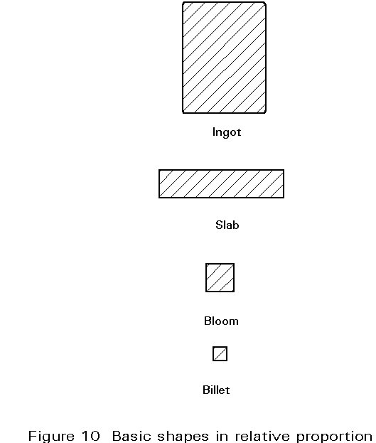
The first hot-rolling operation is to convert ingots into the basic shapes shown in Figure 10. This is generally carried out on a large single-stand, two-high reversing mill, known as a primary or roughing mill. In between the steelmaking plant and the primary mill there is a bay for stripping moulds from the ingots and a battery of soaking pits. Each pit may hold up to 150 tons of ingots and serves to bring the ingots up to a uniform temperature for rolling and to act as a reservoir to accommodate fluctuations in the flow of ingots. Normal practice is to charge ingots into the soaking pits immediately after stripping from the moulds whilst they are still hot. Soaking pit temperatures are generally controlled at 1300°C.
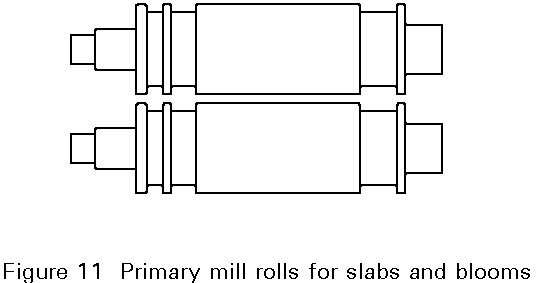
Primary mills are equipped with manipulators for positioning and turning the ingots to enable work to be done on each face as rolling proceeds. Roll grooves (Figure 11) are arranged to enable a variety of basic shapes to be made. Leaving the primary mill, the ends of the bar must be removed (cropping), as they have an irregular shape and this zone concentrates segregation, piping and other defects. The amount to be cropped varies depending on the type of steel (rimmed, killed, etc), the type of casting (direct, bottom casting, hot topping, etc.) and above all on the quality of the finished product.
The bar or beam blank, after cropping, is fed in some cases is directly for rolling into another mill to produce billets or finished sections such as rails or structural sections. More usually the bar is sheared to a set length and passed into stock to be inspected and conditioned, prior to reheating and rolling into finished products at other mills.
Primary mill outputs typically range from 500.000 tonnes to 5 million tonnes per year.
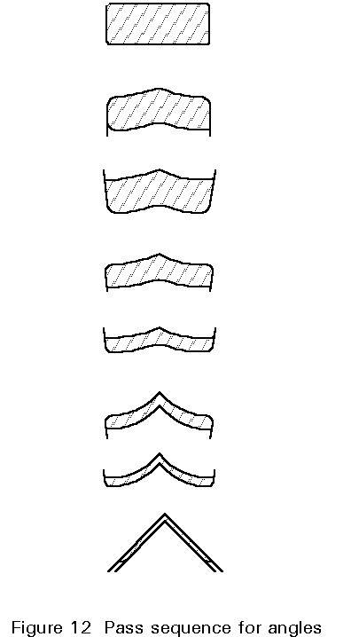
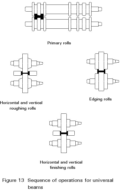
The finish rolling of products for construction work divides broadly into four groups: plates, structural sections, merchant bar and strip. Structural sections comprise standard shapes, e.g. beams, channels, angles, bulb flats, and special sections. As a general rule, large sections are rolled directly from ingots, intermediate-size ones from reheated blooms, and small sections from reheated billets. In all cases the process begins with roughing down, in which the initial square or rectangular cross-section is gradually shaped in successive roll passes into an outline of the required product. This process is followed by finish rolling in successive passes to give the final standard shape and dimensions after cooling. Finishing mill rolling temperatures are usually in the region of 900 - 1000°C. An example of the pass sequence for angle rolling is given in Figure 12. The rather more specialized method for universal beams and columns is shown in Figure 13. Subject to mill size and type, section mill outputs are typically from 200.000 to 1 million tons per year.
Merchant bar is a traditional term for small cross-sections such as rounds, squares, hexagons, flats, etc. which are rolled from reheated billets from continuous in-line mills with as many as 23 rolling stands. Feedstock is generally 100 mm square billet and pass sequences are of a square, diamond, or oval type, culminating at the last mill stand with the finished cross-section.
The production of hot-rolled strip is, in many aspects, an extension of plate rolling, with thicknesses in the range of 2-16 mm and widths up to 2 m. Modern mills are fully instrumented and computer-controlled to give a high standard of dimensional accuracy and finished properties.
These processes can be divided into two basic groups, traditional hot rolling and controlled rolling. In traditional hot rolling, the object is to produce the required shape with the minimum number of roll passes. In controlled rolling, the objective is to increase the strength and toughness of the steel by careful control of temperature and deformation during rolling.
Hot rolling
In traditional hot rolling, temperatures are kept to a maximum so as to reduce the hot strength of the steel and allow large reductions in each roll pass. Because of the high temperature, rapid recrystallization and grain growth occurs between consecutive passes and consequently no grain refinement is achieved. Today, this process is only used for primary reduction and for low-quality steels where there are no specific requirements for strength and resistance against brittle fracture.
Controlled rolling
In the 1960's and 1970's, new application fields, such as nuclear power stations and offshore platforms, demanded structural steel components having improved properties and higher reliability than had been previously available. For North Sea offshore structures, erected in hostile environments including deep waters, severe storms and low service temperatures, not only was strength important, but so was resistance to brittle fracture. Attention was also focused on fabrication properties; easy weldability of steel components under difficult conditions had to be guaranteed. At that time, it became clear that the traditional hot rolling process was unlikely to achieve these requirements and so new production technologies, such as controlled rolling, appeared.
Controlled rolling is a generic term for rolling procedures in which the temperature and deformation during rolling are controlled to achieve desired material properties.
Controlled rolling includes:
× Accelerated cooling
× Quenching and Self-Tempering
Normalizing Rolling
Normalizing rolling is a thermomechanical treatment during which the final deformation is carried out in the normalizing temperature range (» 950°C). The austenite phase completely recrystallises between passes but, because of the reduced temperature, does not experience grain growth. Consequently, after the final pass, air cooling produces a material condition equivalent to that obtained after normalizing. The abbreviated designation of this delivery condition is N.
Normalizing rolling can be performed on nearly all mills because the final rolling takes place at relatively high temperatures (³ 950°C) such that the power and load capacity of the rolling mill is not exceeded.
Thermomechanical Controlled Rolling
Thermomechanical Controlled Rolling (TMCR) is a thermomechanical treatment in which the final deformation is carried out in a temperature range where austenite does not recrystallise significantly. On subsequent cooling, the deformed austenite grain structure leads to a final fine grain ferrite-pearlite microstructure. Usually, the final forming takes place at temperatures just above that at which austenite begins to transform into ferrite. Thermomechanical controlled rolling leads to a material condition which cannot be achieved by heat treatment alone. The resulting grain refined steel shows very desirable toughness properties down to low temperatures for a medium range of product thicknesses and yield strengths.
For several years there has been an increased demand for rolled steel products with yield strengths up to 500 N/mm2 and in large thicknesses, combined with improved fabrication properties. As TMCR cannot be exploited any further because the mechanical power of the rolling mills is limited, new production technologies have had to be introduced.
Accelerated Cooling
Accelerated (water) cooling is performed after the final deformation in order to improve mechanical properties by refining the microstructure. This process has a positive influence on strength as well as on toughness properties and allows the alloy content to be lowered compared to TMCR alone. The microstructure of accelerated cooled steels consists mainly of fine-grained ferrite + pearlite and ferrite + bainite, showing low ductile to brittle transition temperatures, i.e. good toughness.
Quenching and Self-tempering
In the Quenching and Self-Tempering (QST) process, intense waterspray cooling is applied to the surface of the product after the last rolling pass, so that the skin is quenched. Cooling is interrupted before the core is affected by quenching and the outer layers are then tempered by the heat flow from the core to the surface during a temperature equalization phase. The QST process has resulted in the creation of a new generation of steel products with high yield strengths up to 500 N/mm2 and excellent low temperature toughness properties, which are weldable without preheating. Such steels offer important advantages in terms of weight savings and fabrication costs compared to conventionally produced grades.
Influence of rolling conditions on mechanical properties of the steel
The dominant mechanical properties of steel are tensile properties, i.e. yield strength, tensile strength and elongation, and toughness or resistance against brittle fracture. Both properties can be influenced to a large degree by the applied rolling conditions which determine the final grain size and structure (ferrite/pearlite or tempered martensite/bainite).
The main parameters which influence the microstructure and properties are as follows:
× slow (air) cooling at a rate of less than 1°C/s has little influence on mechanical properties: grain size and structure are determined by the preceding rolling
× accelerated (water) cooling at a rate higher than 1°C/s but not high enough to quench the product to form martensite. This process produces a further refinement of the grain size of the ferrite/pearlite structure, substantially improving toughness and increasing tensile properties
× quenching and self-tempering (QST), which produces tempered martensite in the surface layers and a fine-grained bainite/ferrite/pearlite structure in the core area. This process increases tensile strength by 120 to 150 N/mm2 relative to the untreated state and substantially improves toughness.
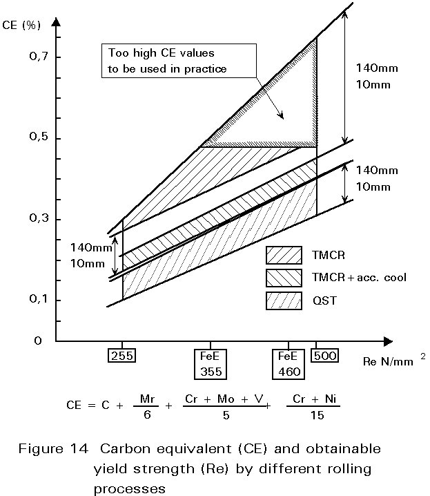
Depending on the rolling process, the chemical composition of the steel has to be adjusted to obtain the different steel grades. Figure 14 shows, in terms of carbon equivalent, the alloy content of the steel necessary to reach yield strengths of 255 to 500 N/mm2 for product thicknesses up to 140 mm. The traditional hot rolling process demands not only the highest alloy contents but it is also not able to cover the whole range of product thicknesses. A lower alloy content and practically the whole range of product thicknesses can be obtained by combining TMCR rolling and accelerated cooling.The lowest alloy content, as well as the full range of modern structural steel products, can be obtained by a combination of TMCR rolling and quenching and self-tempering (QST). By this process route it is not only possible to produce high strength steels in a most economic way but these steels also have excellent weldability due to their low alloy content.
Concerning toughness or resistance to brittle fracture, the poorest characteristics are obtained by traditional hot rolling, which produces steels with ductile to brittle transition temperatures limited to 0°C and higher. Such material characteristics are inadequate for many applications in modern steel construction, especially in cases of larger product thicknesses and higher yield strengths. By combining TMCR rolling with accelerated cooling or with quenching and self-tempering, it is now possible to fulfil these demands. With the accelerated cooling route, and especially the TMCR/QST route, steel can be produced with yield strengths up to 500 N/mm2 and transition temperatures lower than -60°C. These characteristics are sufficient to cover the most stringent specifications arising from high technology areas such as the offshore industry or high-rise building construction.