ESDEP WG 11
CONNECTION DESIGN: STATIC LOADING
To describe the means of achieving moment resisting connections in continuous frames.
Lecture 11.1.1: Connections in Buildings
Lecture 11.1.2: Introduction to Connection Design
Lecture 11.3.1: Connections with Non-Preloaded Bolts
Lecture 11.3.2: Connections with Preloaded Bolts
Lecture 11.3.3: Particular Aspects in Bolted Connections
Lecture 11.7: Partial Strength Connections for Semi-Continuous Framing
This lecture discusses the requirements of rigid moment resisting connections for frames analysed elastically and full strength moment resisting connections for frames analysed plastically. It describes the means of forming such connections using bolts and/or welds. It summarises the design of full strength connections, reviewing the design approaches in Annex J of EC3. Because of their popularity it draws attention to the particular arrangements for portal frame eaves and apex connections.
Building frames can be designed without moment connections. 'Simple Construction', in which the connections are 'nominally pinned' and lateral resistance is provided by some form of bracing, is economical and popular.
However, there are many practical structures in which moment-resisting connections are necessary. Unbraced frames are an obvious example, but even in braced frames there may be a requirement for a cantilever or a midspan beam splice. In high rise frames continuity can be advantageous in controlling lateral deflection.
Moment connections are usually required to transmit shear force - and sometimes axial force - as well, but in practice moment tends to be the prime concern.
'Continuous' framing implies connections which are sufficiently 'performing' (in terms of stiffness and/or strength) for their influence on frame behaviour to be ignored. In other words, they are acceptably close to the theoretical 'ideal' connection, and their characteristics need not be part of the input for the global analysis.
Not all moment connections qualify. Those which do not are classed as 'partial strength' or 'semi-rigid' and are the subject of Lecture 11.7.
This Lecture is concerned with connections which are 'Full Strength' and/or 'Rigid'.
Classification of moment connections is covered in Lecture 11.1.1 Connections in Buildings.
In this section, recall that the method of analysis determines which attribute is relevant.
Elastic global analysis implies Rigid connections.
Plastic global analysis implies Full Strength connections.
Although many practical connections would quality as both Rigid and Full Strength, it is important to recognise that this is not essential.
An elastically analysed continuous frame could incorporate connections which are Rigid and Partial Strength, (provided of course that they are sufficiently strong to resist the moment which results from the analysis).
Similarly, a plastically analysed continuous frame could incorporate connections which are Full Strength and Semi-Rigid (though it might be necessary to take account of connection flexibility when serviceability and stability are under consideration).
Some of Eurocode 3's predecessors have obscured this important distinction.
Notably, the word 'Rigid' has been expected to do double duty, being applied to all connections for continuous framing. (In some contexts, it is even used to mean no more than 'resistant to rotation, i.e. not pinned.) In Eurocode 3, and in ESDEP, it applies strictly to the rotational stiffness of the connection.
Traditionally, nearly all moment-resisting frames have been designed as continuous. Semi-continuous design has been eschewed on account of additional complexity in the analysis process, but may become more popular in the future (Lecture 11.7 covers it). Continuous design - be it elastic or plastic - prevails in practice. Designers therefore seek to ensure that connections are Rigid or Full Strength.
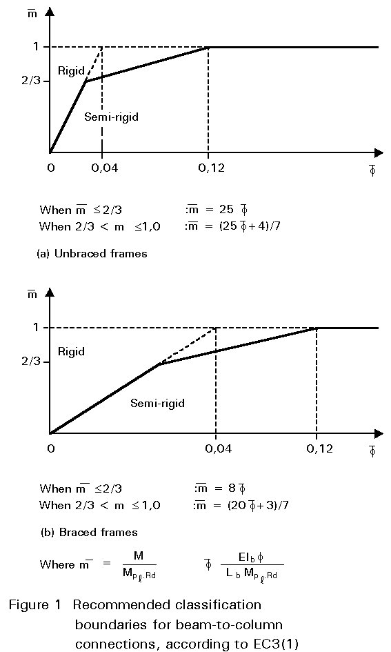
Both these attributes are relative to the connected member. A connection might be full strength relative to a beam which is S275 but not to a beam which is S355. It might be Rigid if the beam is 10m long, but not if the beam is 8m long. Eurocode 3's 'Rigid' standard is considerably more demanding in the case of an unbraced frame, as can be seen from Figure 1 (which reproduces Fig. 6.9.8. of the standard).
Finally, it should be noted that the importance of the continuous/semi-continuous distinction is confined to hyperstatic (indeterminate) frames. When the situation is statically determinate the connection can be designed for strength alone.
Many of the features which make a connection Rigid also make it strong. In practice, a connection designed to be Rigid may be indistinguishable from one designed as full strength, and as already mentioned, it may very well be both. Nevertheless, the correlation between strength and stiffness is far from perfect.
A full strength connection can generally be achieved by welding, using stiffeners as necessary. Indeed, it is advisable (statically determinate situations excepted) that welded connections should generally be designed as full strength, since undersized welds may fail in brittle fashion if exposed to greater than expected moment resulting from (e.g.) differential settlement.
In bolted connections, it is all but impossible to achieve a full strength connection within the depth of the beam. Bolts outside the tension flange, e.g. in an extended end plate, can deliver full strength up to medium depth beams; the limit depends on the strength of the beam and the bolts but is commonly around 4-500mm. (Incidentally, 'high strength' bolts - 8.8 or 10.9 - are practically obligatory in moment connections, and designers must often resort to M24 or even larger sizes.) Beyond this depth it is necessary to increase the lever arm, by welding on a haunch or gusseted extension. Haunches are commonly almost as deep as the beam itself (frequently they are cut from the same section), but such deep haunches are not always necessary.
The possibility that the beam will be significantly overstrength (making the 'full strength' connection into a 'partial strength' one) should not be overlooked. Eurocode 3 suggests that overdesigning the connection by 20% would avert this risk, but this is easier said than done. It would be reasonable to adopt a conservative approach to sizing the components particularly at risk, which are the bolts and welds.
Calculating the moment resistance of a connection, to verify that it qualifies as 'full strength', is a routine procedure and one whose results can be regarded with a fair degree of confidence. The same cannot be said of the rotational stiffness classification. In principle, this can be calculated numerically, and Eurocode 3 Clause J.3.7 gives a formula for application to end plate connections. It should be noted that the present (ENV 1993) formula gives inconsistent results, and is likely to be changed in the definitive version. In practice, as mentioned in the preceding section, a qualitative judgement remains the almost universal approach.
What are the features that make a connection 'Rigid'? Perhaps it is more instructive to approach from the opposite direction, and consider what features introduce flexibility. The flexibility of the connection is the sum of the component flexibilities, and one or two unduly flexible components can overshadow the rest.
Direct load paths are best, involving axial tension or compression, not bending, in the components. For this reason, virtually all the usual types of welded connection, certainly all fully stiffened ones, will qualify as Rigid. It is in bolted connections that flexibility is hard to avoid.
Where bolts are subject to shear, and are not preloaded, some degree of slip is to be expected. If this occurs on the moment resisting 'load path' of a connection, it can hardly be regarded as Rigid. For this reason, axially loaded bolts are favoured in moment connections, and bolts subject to shear (such as those in cover plated splices) should be preloaded if the connection is required to be Rigid.
A bolt loaded in tension subjects the plates it passes through (such as the end plate and the flange of the column) to bending. To minimise flexibility, it is advantageous to:
In practice, provided that the bolt layout is 'compact' and the plates passed through are equal in thickness to the bolt diameter, all haunched connections and most extended end plates are commonly regarded as Rigid. Flush end plates are debatable. Some designers would ensure that the connection achieves a minimum of 60% of full strength, or some other proportion. In doing so they are appealing to the correlation between stiffness and strength. Although this is imperfect, it must be conceded that practical alternatives are elusive.
Eurocode 3's very much more rigorous criterion for unbraced frames - over three times as much stiffness as demanded for the 'Rigid' appellation - is incompatible with current practice, which tends not to distinguish between braced and unbraced frames. It is important to understand that in both cases there is no implication that the frame suddenly ceases to perform if one or more of its connections do not meet the qualifying standard. All that it means is that connection flexibility must be taken into account in the global analysis. In other words, semi-rigid analysis is called for.
Most building frames consist of vertical columns and horizontal beams. It is a fact of life for the connection designer that the members have to be connected at peak moment regions where the beams meet the columns*. Normally these members occupy the same plane - it would be difficult to transmit moment between them if they did not - and only one can pass through the connection uninterrupted. Because the column has axial compression as well as moment to bear, it is given precedence in multistorey construction.
There may also be a requirement for end-to-end column splices to be designed as continuous.
The feet of columns may be connected to the concrete substructure by moment connections. It is perhaps more usual to treat this joint as nominally pinned. However, provided the substructure and, if necessary, the soil, can resist the moment (and do so 'Rigidly' if elastic analysis so demands), a 'fixed foot' may be designed.
End-to-end beam splices are occasionally required; sometimes it is necessary for one beam to cross another, at the same level, in another direction. In these cases the requirement may be to transmit moment from one member to its continuation, shear alone being transmitted to the beam 'passed through'.
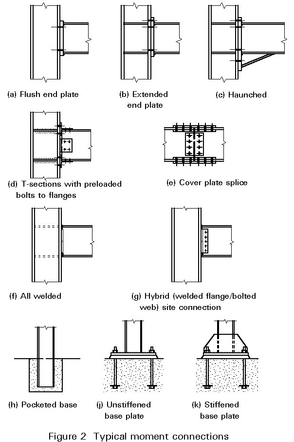
The popular bolted moment connections used in practice are:
For base connections (to concrete) a variant of the end plate connection is generally used, though pocketed connections (in which a suitable depth of the column is simply embedded in the concrete) can be chosen.
Popular welded moment connections are:
Figure 2 illustrates a selection of these connection types.
This discussion has related specifically to moment connections. For more general discussion on the relative merits of welded and bolted connections of different types, reference should be made to Lecture 11.1.2: Introduction to Connection Design.
All moment connections are designed for strength in the same way, irrespective of whether they are required to be Rigid or full strength. The process is one of ensuring that all the components of the connection are capable of resisting the effects of the applied moment. Simultaneously, the connection is usually required to resist an applied shear force, and sometimes an axial force, but more often than not moment is dominant.
Take as an example a typical beam-to-column connection. Moment is transmitted by coupling compression at or near bottom flange level with tension in the upper part of the connection. In the absence of axial force in the beam these two forces are equal.
In a welded connection, it is customary (and not too far from the truth) to assume that the tension and compression are concentrated in the flanges. Although this assumption, in a connection at or near full strength, violates the yield criterion, there is experimental justification for it. In the welded flange/bolted web connection, a hybrid type popular in North America, the 'overstress' in the beam flange may (depending on the section) exceed 40%.
In a bolted connection the upper bolts must resist the tension, and the compression is usually assumed to be transmitted by direct bearing of the bottom flange.
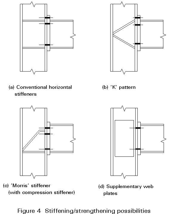
A number of other components may limit the strength of the connection, and Figure 3 illustrates those which apply to an end plate connection. Each must be checked in turn. In some cases a deficiency can be remedied by adding 'stiffeners' (strengtheners, really) or some other form of reinforcement. Examples are shown in Figure 4.
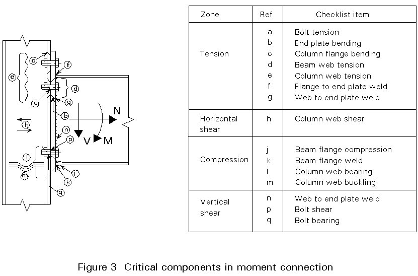
The web of the column is subject to concentrated lateral forces in the tension and compression zones, and is checked using empirical formulae which prescribe an effective area of web. In the compression zone, buckling as well as crushing must be checked. For this purpose restraint from surrounding structure will usually justify an effective buckling length of 0.7 ´ depth between fillets of column.
Shear in the column web panel can be significant, particularly in a one-sided connection or in an unbraced frame. On the other hand, in a two-sided connection in a braced frame, the effects induced by the two opposing beams may partially or completely balance out. Depending on the type of frame, therefore, this component may either be governing or insignificant.
Rules for the detailed checks touched on above are available in Eurocode 3 Annex J, for both welded and bolted end plate connections. They are largely self explanatory; the scope of a single lecture cannot embrace them, and the rules for stiffeners and other forms of reinforcement (such as supplementary web plates), in detail.
However, the procedures for determining the distribution of bolt force in end plate connections with multiple tension bolt rows are anything but self explanatory. The commentary which follows describes the principles; more detail can be found in Lecture 11.4.4.
The force a bolt row can transmit (its 'potential resistance') may be limited by either the plate passed through, the strength of the bolt itself or a combination of the two. If the plate (which may be either the column flange or the end plate) is thin, it will deform by bending. If it is thick, the bolt will break before the plate has yielded. In the intermediate thickness range, the failure mechanism involves yielding of both the plate and the bolt.
Plate bending is complex and three-dimensional in nature. To make the problem tractable, Eurocode 3 introduces the 'equivalent T-stub' approach. Semi-empirical formulae give the length of T-stub which is supposed to correspond to the actual pattern of yield lines for both single bolt rows and groups whose yield patterns combine. This T-stub is free from stiffeners, beam flanges and other complications; their effects have been allowed for in calculating its length. It bends in two-dimensional fashion, along lines parallel to its web.
The three modes of failure described above can now be visualised rather simply; see Figure 5. The first, labelled Mode 1, involves 'double bending' along the bolt line and adjacent to the fillet. Mode 2 combines yielding of the bolts with a single yield line at the fillet. Mode 3 is bolt failure alone. The modal formulae result from simple plastic theory and statics, and naturally it is the one which gives the lowest effective bolt force which governs.
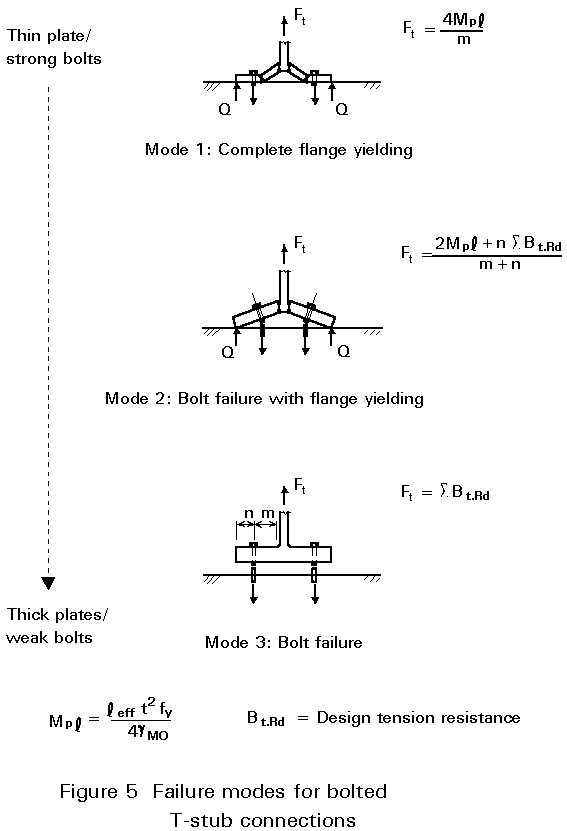
It may be noted that only in Mode 3 is the full resistance of the bolt available; in other modes part of it is ungainfully occupied in resisting prying force. At best, Mode 1 can make available only about 70% of the bolt's tensile value.
What complicates matters is that bolt rows are commonly placed close enough to compete for the available plate bending resistance. Consequently, a pair of bolt rows will mobilise less than twice the force that each could singly, and so on.
Eurocode 3's Annex JJ gives priority to the outer bolt rows which by virtue of their greater lever arm are in a position to convert this resistance into moment more effectively. It can perhaps be more readily understood by inverting the described procedure. The potential resistance of the outer row is calculated as if the other tensile rows were not present. The second row is credited with the potential resistance of rows 1 and 2 taken as a group, minus that of row 1 - or, if less, that of row 2 alone. And so on, considering (in principle at least) all possible groupings. (Stiffeners, if present, restrict the number of rows whose yield patterns may combine.)
At the conclusion of this procedure a set of bolt row potential resistances has been established. They are 'potential' because some other component of the connection (most often in the column web) may limit the total force transmitted. Force is deducted from the innermost row(s) if this is the case.
Finally the connection moment resistance is calculated as S [Fti hi] where Fti is the bolt row force and hi is its lever arm, measured to the centre of compression which is generally taken as coincident with that of the 'bottom' flange.
It should be noted that this calculation is based on a 'plastic' distribution of bolt force, which requires that there is sufficient rotation for the inner tensile bolt rows, as well as the outer ones, to develop their ultimate yield patterns. In connections with multiple bolt rows, this assumption becomes less reasonable as the end plate and column flange thicknesses increase, and both these plates become relatively unyielding.
An alternative procedure is based on a more traditional 'triangular' distribution of bolt force, in which bolt row force is restricted in proportion to lever arm. For this distribution there is no restriction on plate thickness, but at present its use is restricted to full strength connections.
Particularly when more than one load combination must be considered, the design of a moment connection is an involved process. Inevitably, it is based on trial and error. The use of specialist software is recommended, in preference to laborious manual verification. There is also a role for predesigned standard moment connections, whose moment resistance is tabulated by beam size for quick reference.
The pitched-roof portal frame, often plastically analysed, is a very economical and popular building type. Since it is probably the largest market for the type of connections with which this lecture is concerned, it deserves special mention.
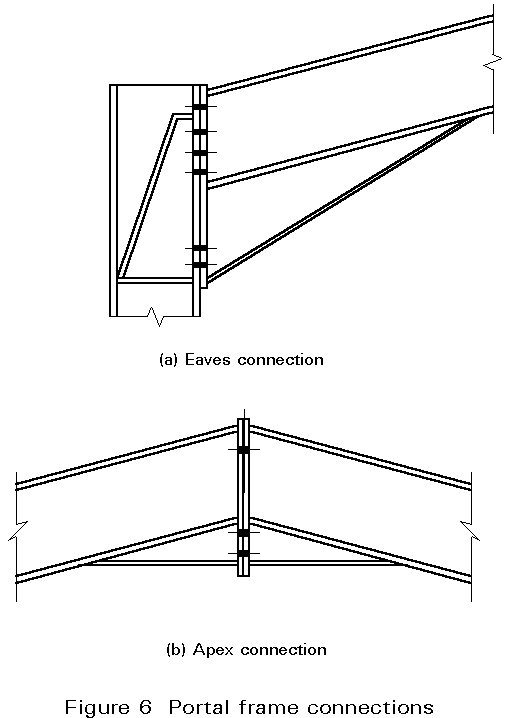
Haunched end plate connections are almost universal in portal frames; these adapt readily to angles of intersection other than 90°. It is customary to make the eaves haunch depth (almost) equal to that of the beam, and to extend it some way along the span. The haunch geometry is determined by overall frame design rather than purely a matter of connection detailing. Apex haunches are usually of more modest size. Figure 6 illustrates typical portal frame connections.
With extended eaves haunches, it becomes a moot point whether the connection is full strength (relative to the plain beam section) or partial strength (relative to the section as increased by the haunch). This is usually resolved by ensuring that the latter is sufficiently 'oversized' to force the plastic hinge to occur at the haunch end, and designing the connection for the maximum moment that this (determinate) situation can induce.
For the usual range of roof pitches, the eaves connection may be designed in the same way as an equivalent 90° beam-to-column connection, with the compression taken as the horizontal component of haunch flange force. Axial compression in the beam will generally be non-negligible; this can be added to bottom flange force with the design moment adjusted to account for its offset.
Except at the interior columns of multi-bay frames, web panel shear is likely to exceed the capacity of the column section. (The column is very likely to be an I rather than an H section.) Stiffeners are usually called for, and a common choice is the 'Morris' stiffener shown in Figure 6a. This acts similarly to a conventional diagonal stiffener, with the advantage that access for the bolts is not impeded.
Additional 'rib' stiffeners may be used to reinforce the column flange between lower bolt rows. The end plate thickness can of course be chosen to avoid the need for such stiffening, but they are sometimes used on the beam side to enhance web tension resistance.
[1] Eurocode 3: Design of Steel Structures ENV 1993-1-1: Part 1.1, General Rules and Rules for Buildings.
[2] Owens, G. W, and Cheal, B. D., Structural Steelwork Connections, Butterworths, Oxford 1989.