ESDEP WG 14
STRUCTURAL SYSTEMS: BUILDINGS
To identify design, construction, cost and fabrication considerations which are specific to non-sway multi-storey steel frames.
Lecture 1A.2: Introduction to Steel's Role in Construction in Europe
Lecture 1A.3: Introduction to Structural Steel Costs
Lecture 1B.1: Process of Design
Lectures 1B.7: Introduction to Design of Multi-Storey Buildings
Lecture 2.4: Steel Grades and Qualities
Lectures 3.1: General Fabrication of Steel Structures
Lecture 3.5: Fabrication/Erection of Buildings
Lecture 4A.1: General Corrosion
Lectures 4B: Protection: Fire
Lectures 5: Computer Aided Design and Manufacture
Lectures 7: Elements
Lectures 11.4: Analysis of Connections
Lectures 3.2: Erection
Lecture 6.3: Elastic Instability Modes
Lectures 10: Composite Construction
Lectures 11: Connection Design: Static Loading
Lecture 14.7: Anatomy of Multi-Storey Buildings
Lecture 14.9: Methods of Analysis for Multi-Storey Frames
The preliminary considerations and the sequence of design of simple frame construction are presented.
Bracing systems (type/location/construction), preferred structural grids, connections (appropriate types for simple frames), the availability of diaphragm action and frame erection, are described.
In discussing the sequence of design, the treatment of loading (permanent, variable, imperfections), beam design (design actions, ultimate and serviceability criteria), column design (design actions, effective length), bracing systems (stiffness requirements, construction details), and connections (classification; category), are covered.
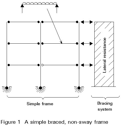
Simple braced non-sway frames probably offer at present the most cost effective structural solution for multi-storey steel buildings. These frames are composed of one or more bracing systems and a simple framing attached to it. The beam-to-column joints are nominally pinned so that the frame is considered to be 'simple'. As a simple frame is not able to resist any horizontal loads, the lateral stability of the entire structure is provided by the bracing system(s), while vertical loads are resisted by both the frame and the bracing system. In most cases, the bracing system's response to in-plane horizontal forces is sufficiently stiff such that the effects of horizontal displacements on equilibrium (second order effects) may be neglected. The structure, therefore, may be classified as non-sway. Figure 1 shows the principal components - simple frame and bracing system - of such a structure.
The fabrication of beam-to-column connections in braced, pin-jointed, multi-storey frames is relatively straight-forward. The connections are fabricated using simple elements without the need for labour intensive welded stiffeners such as are required moment resisting connections.
The current economic trend is such that the ratio of labour cost to that of the material is increasing at an increasing rate (see Figure 2). In addition, direct and indirect labour costs for a typical steel frame constitute as much as 50-70% of the cost of the erected steelwork. As a result, the cost of the increased total weight of a simple steel frame, when compared to a moment resisting equivalent, is often offset by the reduced cost of the steelwork fabrication. In many cases, therefore, simple braced steel frames offer the most cost effective structural solution.

This particular lecture examines the design and construction considerations which are specific to simple braced non-sway frames and demonstrates the design approach which should be adopted in accordance with Eurocode 3 [1].
The multi-storey structure under consideration is composed of two separate
sub-systems, usually a bracing system and a simple frame.
The main purpose of a bracing system is to provide the lateral stability of the entire structure. It has to resist, therefore, all lateral loading due to external forces, e.g. wind, imposed deformation, e.g. temperature, earthquake and the effects of imperfections on the simple bracing. For a non-sway frame, the bracing system must, in addition, be stiff enough so that second order effects need not be taken into account in the analysis. In terms of Eurocode 3 [1], this requirement means that either criterion (1):
Vsd/Vcr £ 0,1 (1)
where Vsd is the design value of the total vertical load on the structure
and Vcr is the elastic critical value of the bracing system for failure in a sway mode
or, for each storey, criterion (2)
![]() (2)
(2)
where d is the interstorey drift
h is the storey height
H is the total horizontal reaction at the bottom of the storey
V is the total vertical reaction at the bottom of the storey (for both the bracing system and the simple frame)
should be satisfied for all load cases under consideration.
Possible configurations of bracing systems as shown in Figure 3 are:
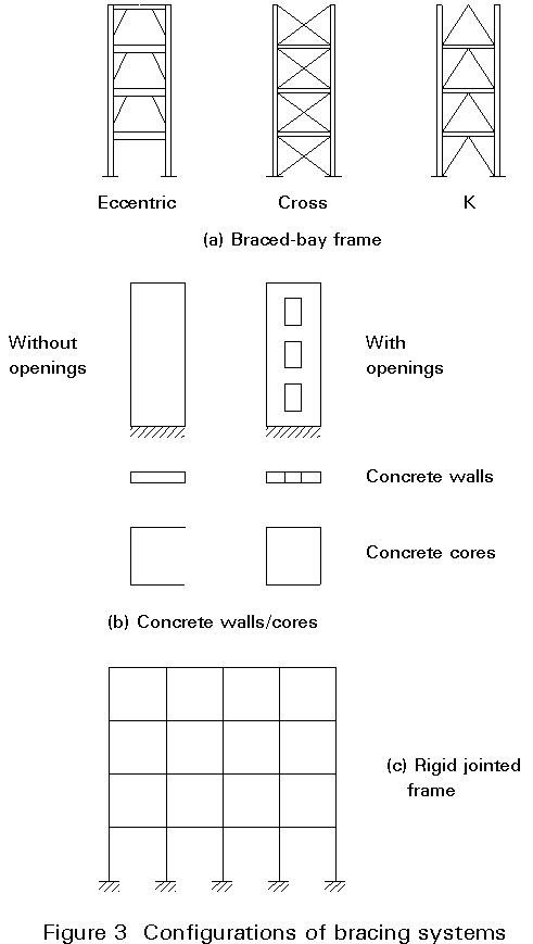
The systems most appropriate for a particular structure depend very much on the structural layout, the availability of service cores, and the effect on the construction programme.
(a) Braced-bay frames (Figure 3a)
Braced-bays are located such that they have minimum impact on the structural layout, but taking into account the manner in which the frame is to be erected, the distribution of horizontal forces and the location of any movement joints in the structure.
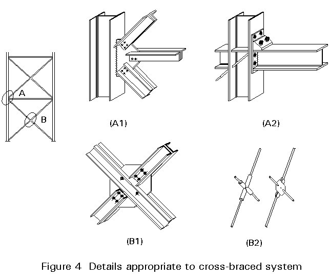
Braced-bay systems comprise diagonal, cross, 'K' and eccentric bracing arrangements. The advantage of triangulated systems is that the bracing elements are subjected only to tension ('cross') or tension and compression ('K' and 'diagonal') in the absence of bending moments. Consequently, the members are relatively light providing a very stiff overall structural response. In the case of eccentric bracing, the system relies, in part, on flexure of the horizontal beam elements. This particular arrangement provides a more flexible overall response which is most effective under seismic loading conditions.
Where a single diagonal (as opposed to 'cross') brace is used, it must be capable of resisting both tensile and compressive axial forces to allow for the alternating direction of wind load. Under these conditions, it is recommended that the bracing member has a minimum slenderness ratio of 250 to prevent the self-weight deflection of the brace limiting its compressive resistance.
Although many different section shapes can be used as compression braces, a circular hollow section is the most efficient structurally. It should be noted that, in addition, hollow sections offer a greater resistance to corrosion and can be more aesthetically pleasing than open sections.
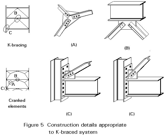
In a cross-braced system, the brace members are required to resist tension only. Consequently, very light, solid tie-bars or flats can be used. Figure 4 illustrates fixing details appropriate to cross braced systems whilst Figure 5 shows construction details appropriate for K-braced systems.
(b) Reinforced concrete shear walls and cores (Figure 3b)
Shear walls are constructed from reinforced in-situ concrete and are positively connected to the steel structure to resist horizontal forces. Such walls often serve a second important function of compartmenting the structure to limit the spread of fire.
Concrete cores are provided in multi-storey structures to house lifts, stairwells and service ducts.
Both concrete shear walls and cores may be provided with or without openings depending on the functioning requirements of the building.
(c) Rigid jointed frames
In cases where braces or concrete walls would disturb the functioning of the building, rigid jointed moment resisting frames may provide the lateral stability of the building.
The design of such frames is described in Lecture 14.14.
The location of the bracing systems in plan within the structure will influence the efficiency with which the lateral forces can be resisted. The most appropriate position for the bracing systems is in the periphery of the building (Figure 6a) since this arrangement provides the largest overall torsional resistance. The minimum number of bracing planes required for the provision of translational and torsional stability is 3. These planes should not meet at one point since this could be a pole of rotation.
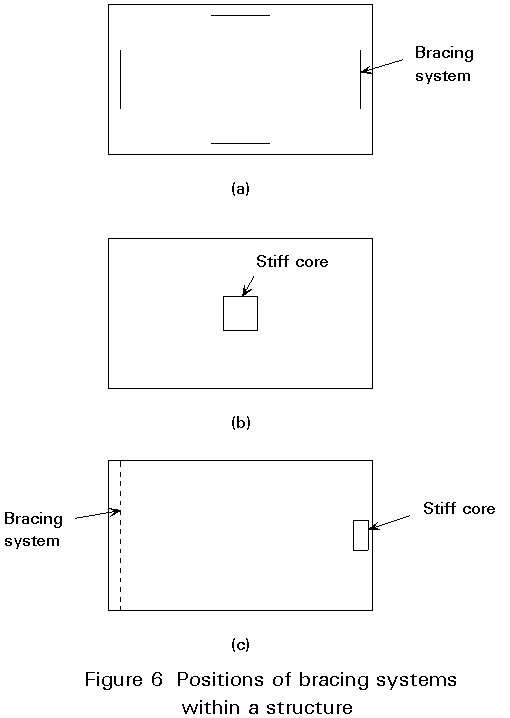
When stiff cores are used, they should preferably be located in the centre of the building (Figure 6b), since it can expand freely in both directions. The torsional stability is then provided by the torsional rigidity of the core.
In some cases eccentrically placed service cores in conjunction with supplementary bracing systems are present (Figure 6c). In that case the possibly different flexibilities of the bracing systems and the core must be taken into account in the analysis, since the stiffer element will attract a larger share of the applied horizontal load.
The simple frame consists of a series of beams and columns, forming a structural grid. The elements of the simple frame are assumed to resist gravity loads only.
(a) The structural grid
Usually the layout of the structural grid is dictated by the intended use of the structure and architectural requirements. Notwithstanding this, there are a number of factors to be borne in mind when choosing column spacings in a simple frame.
In all structural framing, the greatest cost effectiveness can be achieved through a high repetition of similarly fabricated components. Essentially, a regular column grid is significantly less expensive than a non-regular grid for a given floor area, see Figure 7.
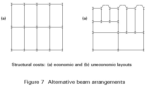
Not surprisingly, orthogonal arrangements of beams and column grids, as opposed to skewed, result in the most cost effective layout. In addition, the greatest economies can be achieved when the column grids are rectangular - not square. In this configuration, the secondary beams should span in the longer direction and the primary beams in the shorter. This arrangement has the effect of reducing to a minimum, the number of beam-to-beam connections and the number of individual members per unit area of supported floor.
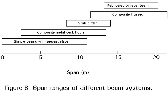
By definition, the beams in a simple frame are assumed to be simply supported between columns. The most cost effective maximum span will be dependent on the applied load, the type of beam system employed and the restrictions on structural floor depth. This latter consideration will be influenced by restrictions on overall building height and the requirements for services either above or below the structural floor zone.
Lecture 14.7 introduced the different types of floor and beam construction which are commonly in use. Figure 8 shows the practical span ranges for these different systems when used in office construction. Not surprisingly, systems in which the structural steel members act compositely with an in-situ concrete slab achieve the longest spans.
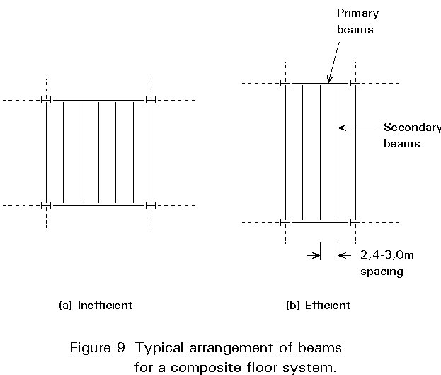
Columns are conventionally located at spacings in multiples of 2,5m or 3,0m (e.g. typical bay sizes 9m x 6m, 7,5m x 15m etc). This latter dimension conforms with the approximate maximum span of conventional steel permanent formwork (as used in composite construction) when unpropped. Figure 9 shows typical arrangements of primary and secondary beams supporting a composite floor using permanent decking.
(b) Connections
As discussed above, the beam-to-column and beam-to-beam connections are assumed to function as 'pins' and should therefore be detailed accordingly. It should be noted that a 450mm deep steel 'I' section spanning 6m experiences a 10mm shift between the upper and lower flange at the connection when subjected to the ultimate uniformly distributed load (Figure 10). Consequently, connection details should be adopted which can accommodate this magnitude of rotation without transferring significant moment.
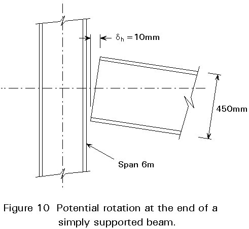
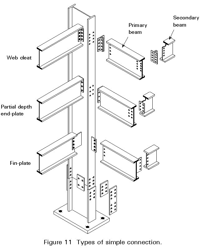
Figure 11 shows three connection types which satisfy this criterion - namely web cleat, fin plate and partial-depth end-plate connections.
The design moments in columns of simple frames tend to be rather small when compared to the axial compression. Consequently, bearing and end-plate splice connections and nominal 'pin' base connections (see Lecture 11.5) are used extensively.
Access restrictions permitting, column splices should be provided at 12-16m intervals along the column, with the splice located at approximately 500mm above the nearest structural floor level. Columns splices are particularly expensive to fabricate. There is invariably greater economic advantage in retaining a heavier column section through a number of levels rather than introducing a splice to reduce the weight of the upper column segments.
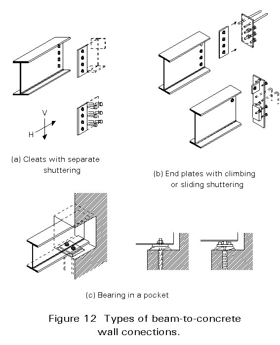
Simple beam-to-concrete walls/cores connections should be able to carry loads as soon as the connection is made. Some connection types that may be used for such cases are shown in Figure 12 as follows:
· Projecting cleats are embedded in the wall (Figure 12a).
· Steel components are embedded in the wall and connector elements are welded to them on site (Figure 12b).
· Pockets are made in the core wall in which the ends of the beams engage (Figure 12c).
Floors should be able to transmit the vertical loads to the supporting framing beams. However, in the multi-storey simple, braced frames discussed here, lateral loads applied to the external envelope of the building should be transferred to the vertical bracing systems. This transfer occurs via diaphragm action of the floors. Consequently, the floors in these frames have, in addition, to transmit horizontal loads.
The adequacy of the floor to act as a diaphragm depends very much on the type of floor system employed. Pre-cast concrete floor planks with a non-structural screed have limited resistance to the racking effects of diaphragm action. In such cases, supplementary bracing systems in plan are required to distribute lateral forces adequately. Supplementary bracing systems can result in a significant increase in fabrication costs and, as such, should be avoided. Where precast concrete floor units are employed, sufficient diaphragm action can be achieved in most cases by using a lightly reinforced structural concrete topping.
Composite concrete floors, incorporating permanent metal decking, provide excellent diaphragm action. In addition, it should be noted that a correctly fixed decking, with the appropriate side lap stitching, provides an adequate floor diaphragm during the construction stage.
The loads to be considered for the analysis of multi-storey buildings are:
- structural elements
- secondary non-structural elements
- services
The effects of imperfections should be allowed for in the analysis of the frame in the form of an initial sway imperfection f determined from:
f
= kc ks fo (3)where f = 1/200
kc, ks are factors depending on the number of storeys and columns per plane.
These imperfections are usually accounted for in the form of equivalent horizontal forces FH at floor levels according to:
FH = f Fs (4)
where Fv is the design vertical load at the floor level under consideration.
The design includes verifications in two different limit states, the serviceability limit state and the ultimate limit state. The most usual combinations of actions for the type of buildings under discussion are:
Beam deflections
Frd = G + Q (5)
Frd = Q
(6)
It should be noted that the deflection limits are different for the combinations (5) and (6)
Frd = G + y1 Q (7)
VHd = W (+ FH from Equation (4)) (8)
For the simple frame -
FHd = 1,35 G + 1,5 Q (9)
For the bracing system -
Vr,H,d = 1,35 G + 1,5 Q + yo 1,5 W (10)
= 1,35 G + 1,5 yo Q + 1,5 W (11)
= G + Q + E (12)
Detailed information on the combination rules is provided by the relevant rules of Eurocodes 1 [2], 3 [1] and 8 [3].
Beams are designed as simple spans, neglecting any continuity at the supports. When the beam moments and shears are known from the analysis, the beam dimensions may be determined according to the provisions of Eurocode 3 [1] for steel beams or Eurocode 4 [4] for composite beams.
It should be noted that most conventional types of floor slab construction will provide adequate positional restraint to the top (compression flange) of the beam. Consequently, the beams can be designed without taking into account reductions in moment resistance due to lateral-torsional buckling effects.
Under the full characteristic loading (load factors equal unity), the total central deflection of the beam, dmax (Equation (5)), and the deflection of the beam due solely to imposed load (Equation (6)), d2, should satisfy the limits in Table 4.1 in Eurocode 3 (reproduced here as Table 1). It should be noted that the deflection check is performed using the 'rare combination' of loading (Equation (6)).
Depending on the use of the structure, it is necessary to check the dynamic sensitivity of the floor beams. Clause 4.3.2 of Eurocode 3 states that, where the total deflection of the beam is less than 28mm, the dynamic sensitivity is satisfactory for foot traffic (walking), and when less than 10mm, the sensitivity is adequate for rhythmic loading (dance floor). It should be noted that these limits are based on a 'frequent' combination of loading (Equation (7)).
When assessing the deflection and dynamic sensitivity of secondary beams, it is important to include that component due to the deflection of the supporting beams.
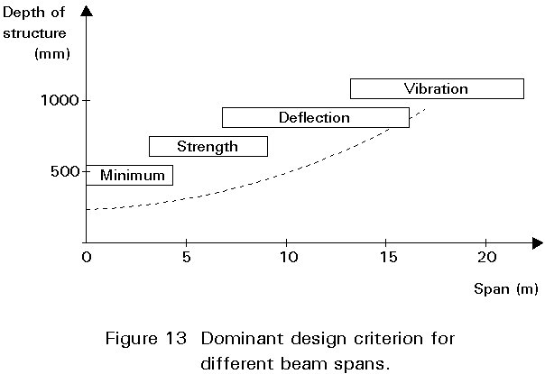
Whether it is the strength, deflection or dynamic sensitivity which controls the design will depend on the span-to-depth ratio of the beam. Figure 13 gives typical span ranges for beams in office buildings for which these design criteria (strength, deflection, vibration) may be dominant.
The ultimate axial load in columns is derived from the cumulative total of the ultimate support reactions from those beams which frame into the column.
Although there is assumed to be no direct transfer of bending moment from the beam to column, it is a requirement in most European countries that a nominal moment is transferred. This moment is assumed to be equal to the vertical beam reaction multiplied by the offset to the interface between the beam and the column. For a beam connection to the major axis of the column, this offset is equal to half the depth of the column. In certain countries, an increased eccentricity of beam reaction is considered, e.g. in the U.K. the eccentricity of a major axis connection is assumed equal to Dc/2 + 100mm. In all cases, the applied nominal moment is divided between the upper and lower column segments in proportion to their flexural stiffnesses.
The precise manner in which simple frames should be modelled and, in particular, the actions to be considered in the column design, will be addressed in the forthcoming Annex H of Eurocode 3 [5].
As the column node points are positionally restrained, the maximum effective column length (Le) for buckling considerations is 1,0L, where 'L' is the length of the column segment. In cases where the adjacent column segments are under-utilised in terms of load resistance, the residual flexural stiffness of these members may result in an effective length of < 1,0L for the segment under consideration.
Such a situation arises where the column section is continuous through a restraint point and the column segments on each side of the restraint point are of different length. Table 2 summaries the reductions in effective length which may be considered for different a/L ratios. However, the location of column splices and the degree of stiffness continuity should be borne in mind when taking this enhancing effect into account.
The effects of patterned imposed loading are not usually considered in the design of the frames. Consideration of patterned loading will depend on the specific requirements in individual countries. However, in cases where nominal moments are applied to the column, it is a requirement that a value of bM.LT = 1,1 (Eurocode 3: clause 5.5.4) is adopted when considering the lateral-torsional buckling of the column. This is a conservative measure which guards against particular patterns of load being applied in the real structure which would cause the column to be subjected to a single curvature moment distribution which is a particularly onerous arrangement in lateral-torsional buckling considerations.
As discussed in Lecture 14.8, the bracing system must satisfy certain criteria in order that the frame may be correctly classified as braced and non-sway.
In Eurocode 3 (clause 5.2.5.3(2)), a frame is 'braced' if the bracing system reduces the lateral deflection of the frame by 80%. Clearly, this criterion will always be satisfied in the case of simple frames which behave as mechanisms in the absence of a bracing system.
Additionally, by satisfying criterion (2) the bracing system is classified as non-sway so that second order effects can be neglected in the analysis.
The stiffness of the bracing system is not only governed by Equation (2) but also, and more often, in the serviceability verification which requires that both the interstorey shifts and the lateral deflections of the structure as a whole must be limited, the limits depending on the sensitivity of the structural elements to shear deformations. The limits recommended by Eurocode 3 [1] are:
h/300 for the interstorey drifts
ho/500 for the structure as a whole
where h is the storey height
ho is the overall height of the building
When considering the ultimate limit state, the bracing system must be capable of safely transferring the factored lateral loads safely down to the foundations. An all steel braced-bay system will, more often than not, comprise a trussed lattice. The design of the internal bracing members is therefore similar to the procedure in Lecture 7.12 which is devoted to the design of lattice girders.
Quite often, a horizontal member in a latticed bracing system serves also as a floor beam. This particular member will be subjected to primary bending (due to gravity loads) and axial compression (due to wind and imperfection load). The resistance of the element should therefore be checked as a beam-column (in accordance with clause 5.5.4 of Eurocode 3) using the load factors appropriate for gravity plus lateral load, as discussed in Section 3.1 above.
Particular care should be taken in the modelling of concrete cores. Some points to take into account are:
(a) The use of the effective width rather than the full width for the flanges if they are very wide (Figure 14). The effective width to be considered for the determination of the bending properties is a function of the b/t ratio of the flange, the building height and the form of the bending moment diagram along the height. Relevant provisions are given in Eurocode 3 [1].
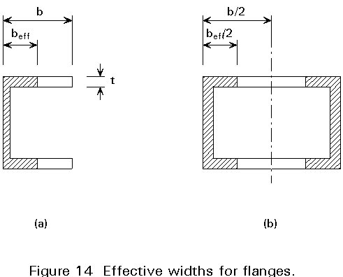
(b) The inclusion of the torsional properties of the cores. The torsional resistance of hollow sections (Figure 14b) is provided mainly rotational torsion, while that of channel or I sections (Figure 14a) mainly by non-uniform, warping torsion, i.e. through opposite bending of the flanges. Depending on the software used, the modelling of the core as a single vertical element should be examined to determine if it is adequate. It may be necessary to introduce more elements to represent the properties of core.
(c) The inclusion in the analysis of the bending resistance which is provided by the staircases between the floors. A staircase provides some resistance to relative floor displacement. Its inclusion leads to a reduction of interstorey drifts but leads to additional reinforcement for the staircase. Models for determining the equivalent static properties of a staircase may be taken from the literature.
The connections should be designed and detailed to prevent excessive transfer of moment between the beams and columns. Such connections should comply with the classification for a 'nominally pinned connection' in terms of both strength and rigidity, see clauses 6.4.3 and 6.4.2 respectively of Eurocode 3 [1].
The beam-to-column and beam-to-beam connections are designed principally to resist the shear due to the vertical beam reaction. Depending on the connection detail adopted, it may also be necessary to consider an additional bending moment resulting from the eccentricity of the bolt line from the supporting face. Invariably, these connections will conform with the Category A: Bearing type designation in clause 6.5.3.1 of Eurocode 3. This category is applicable to connections comprising non-preloaded bolts for which the principal design criteria are the shear and bearing resistance, see Table 6.5.2 in Eurocode 3 [1].
In almost all cases, the connections in simple frames are made on-site using conventional bolts in clearance holes. These bolts slip into bearing when subjected to load. Such connections are used also in those parts of the structure which are subjected to reversible wind loads, e.g. braced-bay frames - see clause 6.3(3).
The design of bolted steelwork connections is presented in full in Lectures 11.
The connections between the various elements in a simple frame are relatively simple to fabricate and can be easily made on site. Consequently, simple frames can be erected very quickly and efficiently.
However, due to the lack of moment transfer between the beams and columns, maintaining the stability of the structure during erection can present a number of problems. Often, it is necessary to incorporate temporary bracing into the structure to provide the necessary lateral resistance until such time as the permanent bracing system is installed. Clearly the layout of the structure and in particular, the location of the permanent bracing systems, will influence the sequence of fabrication, delivery of materials to site and erection. The implications on the construction programme should, therefore, be considered when developing the conceptual design of the main structural frame.
It should be noted that one of the main benefits of using slip formed concrete cores constructed in advance of the steelwork, is that they can totally eliminate the need for temporary bracing.
One of the main issues affecting the efficiency and speed of erection is the number of individual elements. A large number of elements will require extensive use of cranes, a major cost item in the erection process. A structural grid and frame arrangement should, therefore, be selected which reduces to a minimum the number of elements to be erected.
The erection of steel frames is discussed in detail in Lectures 3.2.
[1] Eurocode 3: "Design of Steel Structures": ENV1993-1-1: Part 1.1: General rules and rules for buildings, CEN 1992.
[2] Eurocode 1: "Basis of Design and Actions on Structures"; ENV 1991-1, basis of design (in preparation).
[3] Eurocode 8: "Structures in Seismic Regions - Design" (in preparation).
[4] Eurocode 4: "Design of Composite Steel and Concrete Structures": ENV 1994-1-1: Part 1, General rules and rules for buildings, CEN, 1992.
[5] Eurocode 3: "Design of Steel Structures": Annex H: Modelling of building structures for analysis (in preparation).
|
Recommended limiting values for vertical deflections |
||
|
Condition |
Limits |
|
|
d max |
d 2 |
|
|
Roofs generally |
L/200 |
L/250 |
|
Roofs frequently carrying personnel other than for maintenance |
L/250 |
L/300 |
|
Floors generally |
L/250 |
L/300 |
|
Floors and roofs supporting plaster or other brittle finish or non-flexible partitions |
L/250 |
L/350 |
|
Floors supporting columns (unless the deflection has been included in the global analysis for the ultimate limit state) |
L/400 |
L/500 |
|
Where dmax can impair the appearance of the building |
L/250 |
- |
Table 1: Deflection limits for beams in Eurocode 3
|
Column |
Frame |
0 |
0,1 |
0,2 |
0,3 |
0,4 |
0,5 |
0,6 |
0,7 |
0,8 |
0,9 |
1,0 |
a/L |
|
|
|
0,70 |
0,73 |
0,76 |
0,79 |
0,82 |
0,85 |
0,88 |
0,91 |
0,94 |
0,97 |
1,0 |
Lt/L |
|
|
|
0,50 |
0,53 |
0,57 |
0,61 |
0,65 |
0,70 |
0,75 |
0,81 |
0,87 |
0,93 |
1,0 |
Lt/L |
|
|
|
0,70 |
0,72 |
0,74 |
0,77 |
0,79 |
0,81 |
0,84 |
0,87 |
0,91 |
0,95 |
1,0 |
Lt/L |
Table 2: Effective length of continuous braced columns