ESDEP WG 15A
STRUCTURAL SYSTEMS: OFFSHORE
Lecture 1B.2.2: Limit State Design Philosophy and Partial Safety Factors
Lectures 10.6: Shear Connection
Lectures 12.4: Fatigue Behaviour of Hollow Section Joints
Lecture 15A.12: Connections in Offshore Deck Structures
Lecture 17.5: Requirements and Verifications of Seismic Resistant Structures
A general knowledge of design in offshore structures and an understanding of offshore installation are also required.
In this lecture piled foundations for offshore structures are presented. The lecture starts with the classification of soil. The main steps in the design of piles are then explained. The different kinds of piles and hammers are described. The three main execution phases are briefly discussed: fabrication, transport and installation.
The stratigraphy of the sea bed results from a complex geological process during which various materials were deposited, remoulded and pressed together.
Soil texture consists of small mineral or organic particles basically characterized by their grain size and mutual interaction (friction, cohesion).
The properties of a specific soil depend mainly on the following factors:
For design purposes the influence of these factors on soil behaviour is expressed in terms of two fundamental parameters:
Since the least significant of either of these parameters is often neglected, soils can be classified within "ideal" categories:
Granular soils are non-plastic soils with negligible cohesion between particles. They include:
Clays are plastic soils with particle sizes less than 0,002mm which tend to stick together; their permeability is low.
The nature and characteristics of the soil surrounding a pile generally vary with the depth. For analysis purposes, the soil is divided into several layers, each having constant properties throughout. The number of layers depends on the precision required of the analysis.
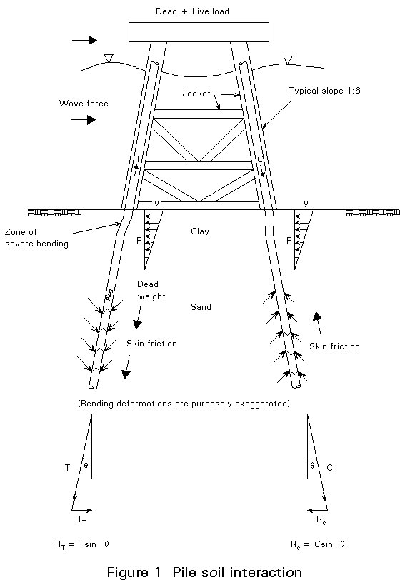
Steel offshore platforms are usually founded on piles, driven deep into the soil (Figure 1). The piles have to transfer the loads acting on the jacket into the sea bed. In this section theoretical aspects of the design of piles are presented. Checking of the pile itself is described in detail in the Worked Example.
These loads are those transferred from the jacket to the foundation. They are calculated at the mudline.
Gravity loads (platform dead load and live loads) are distributed as axial compression forces on the piles depending upon their respective eccentricity.
Environmental loads due to waves, current, wind, earthquake, etc. are basically horizontal. Their resultant at mudline consists of:
The basic gravity and environmental loads multiplied by relevant load factors are combined in order to produce the most severe effect(s) at mudline, resulting in:
The overall resistance of the pile against axial force is the sum of shaft friction and end bearing.
Skin friction is mobilized along the shaft of the tubular pile (and possibly also along the inner wall when the soil plug is not removed).
The unit shaft friction:
Lateral friction is integrated along the whole penetration of the pile.
End bearing is the resultant of bearing pressure over the gross end area of the pile, i.e. with or without the area of plug if relevant.
The bearing pressure:
The pile penetration shall be sufficient to generate enough friction and bearing resistance against the maximum design compression multiplied by the appropriate factor of safety. No bearing resistance can be mobilized against pull-out: the friction available must be equated to the pull out force multiplied by the appropriate factor of safety.
The shear at the mudline caused by environmental loads is resisted by lateral bearing of the pile on the soil. This action may generate large deformations and high bending moments in the part of the pile directly below the mudline, particularly in soft soils.
P-y curves represent the lateral soil resistance versus deflection. The shape of these curves varies with the depth and the type of soil at the considered elevation. The general shape of the curves for increasing displacement features:
For analysis purposes, the soil is modelled as lumped non-linear springs distributed along the pile. The fourth order differential equation which expresses the pile deformation is integrated by successive iterations, the secant stiffness of the soil springs being updated at each step.
For large deformations, the second order contribution of the axial compression to the bending moment (P-Delta effect) shall be taken into account.
Piles installed by driving are forced into the soil by a ram hitting the top. The impact is transmitted along the pile in the form of a wave, which reflects on the pile tip. The energy is progressively lost by plastic friction on the sides and bearing at the tip of the pile.
A considerable number of empirical formulae exist to predict pile driveability. Each formula is generally limited to a particular type of soil and hammer.
This method of analysing the driving process consists of representing the ensemble of pile/soil/hammer as a one-dimensional assembly of masses, springs and dashpots:
The energy of the ram hitting the top of the pile generates a stress wave in the pile, which dissipates progressively by friction between the pile and the soil and by reflection at the extremities of the pile.
The plastic displacement of the tip relative to the soil is the set achieved by the blow. Curves can be drawn to represent the number of blows per unit length required to drive the pile at different penetrations.
The wave equation, though representing the most rigorous assessment to date of the driving process, still suffers a lack of accuracy, mostly caused by the inaccuracies in the soil model.
Driven piles are the most popular and cost-efficient type of foundation for offshore structures.
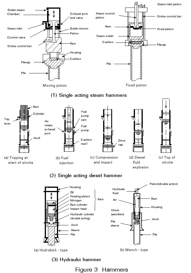
As shown in Figure 2, the following alternatives may be chosen when driving proves impractical:
Piles are usually made up in segments. After placing and driving the first long segment, extension segments called add-ons are set on piece by piece as driving proceeds until the overall design length is achieved.
In recent years one-piece piles have been widely used in the North Sea since the offshore work is considerably reduced.
Wall thickness may vary. A thicker wall is sometimes required:
Uniform wall thickness is however preferable thus avoiding construction and installation problems.
Insert piles are smaller diameter piles driven through the main pile from which the soil plug has been previously drilled out. They are therefore not subjected to skin friction over the length of the main pile and can reach substantial additional penetration.
The insert pile is welded to the main pile at the top of the jacket and the annular space between the tubes is grouted.
This type of pile is used:
× a thicker wall section of the main pile will be within the jacket height instead of below the mudline.
× reduced friction area and end bearing pressure,
× difficulties often noted for the setting-in of all the required volume of grouting, i.e. the concern is the leakage of grout or the impossibility to fill with the calculated volume of grout.
This procedure is the only means of installing piles with tension resistance in hard soils or soft rocks; it resembles that for drilling a conductor well.
An oversized hole is initially drilled to the proposed pile penetration depth. The pile is then lowered down, sometimes centred in the hole by spacers and the annular space between the pile shaft and the surrounding soil is grouted.
Design uncertainty results because:
While belled piles, on land, are used to decrease the bearing stress under a pile, offshore belled piles provide a large bearing area to increase tip uplift resistance.
The main pile, normally driven, serves here as a casing through which a rig drills a slightly oversized hole ahead. A belling tool (underreamer) then enlarges the socket to a conical bell with a base diameter a few times that of the main pile. A heavy reinforcement cage is lowered inside the bell which is subsequently filled with concrete made using fine aggregate (maximum size 10mm).
The piles are usually made up of "cans" - cylinders of rolled plate with a longitudinal seam. Single cans are typically 1,5m long or more. Longitudinal seams of two adjacent segments are rotated 90° apart at least.
Bevelling is mandatory should the wall thickness difference exceed 3mm between adjacent cans. Maximum deviation from straightness is specified (0.1% in length).
Commonly used steel grade is X52 or X60.
The outside surface of grouted piles should be free of mill scale and varnished.
In certain instances, steel piles are protected underwater by sacrificial anodes or by impressed current. In the splash zone additional thickness to allow for corrosion (3mm for example) and epoxy or rubberized coating, monel or copper-nickel sheeting are provided.
Pile segments are choked and fastened to the barge to prevent them from falling overboard under severe seastates. Pile plate should be thick enough to prevent any deformation caused by stacking.
This method is attractive where long segments of pile are to be lifted and set in guides far below the sea surface (skirt piles for example).
The ends of the piles are sealed by steel closure plates or rubber diaphragms which should be able to resist wave slamming during the tow.
The piles are pre-set inside the main legs or in the guides/sleeves, generating additional weight and possibly buoyancy (if closed). They are held in place by shims which prevent them from escaping from their guides during launch and uprighting of the jacket.
Several piles are driven immediately after the jacket has touched down, providing initial stability against the action of waves and current.
Piles are positioned:
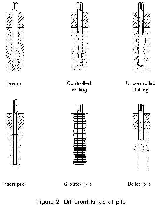
Piles can then be driven using any type of hammer (or a combination of types). Hammers are illustrated in Figure 3.
Steam hammers are widely used for offshore installation of jackets. They are generally single acting with rates of up to 40 blows/minute. Energies of current hammers range from 60 000 to 1 250 000 ft lb/blow. (82KNm to 1725KNm per blow).
During driving, the hammer with attached driving head rides the pile rather than being supported by leads. The hammer line from the crane boom is slackened so as to prevent transmission of impact and vibration into the boom.
Diesel hammers are much used at offshore terminals. They are lighter to handle and less energy consuming than steam hammers, but their effective energy is limited.
Hydraulic hammers are dedicated to underwater driving (skirt piles terminating far below the sea surface).
Menck hydraulic hammers are widely used. They utilize a solid steel ram and a flexible steel pile cap to limit impact forces. They are double acting. Hydraulic fluid under high pressure is used to force a piston or set of pistons, and in turn, the ram up and down.
Properties of some hammers used offshore are shown in Table 1. A selection of large offshore pile driving hammers driving on heavy piles is also shown in Table 2.
Selection of hammer size is based on:
Typical values of pile sizes, wall thicknesses, and hammer energies for steam hammers are shown in Table 3.
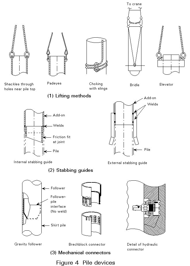
Figure 4 shows the different ways of providing lifting points for positioning pile sections. Padeyes are generally used (welded in the fabrication yard; their design should take into account the changes in load direction during lifting). Padeyes are then carefully cut before lowering the next pile section.
Sketch E shows the different steps for the positioning of pile sections:
Different solutions for connecting pile segments back-to-back are used:
- pile wall thickness: 3 hours for 1in. thick (25,4mm); 16 hours for 3in. thick, (76,2mm) (typical).
- number and qualification of the welders.
- environmental conditions.
- breech block (twisting method).
- lug type (hydraulic method).
Figure 5 shows the different steps of this routine operation:
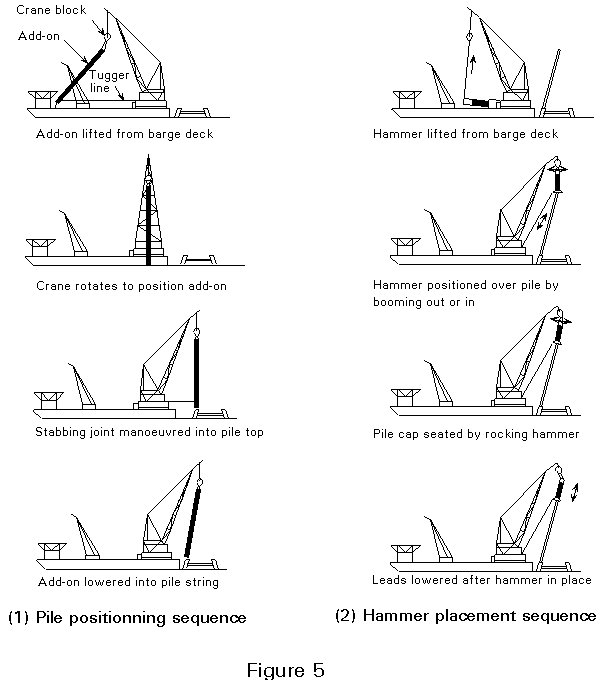
Each add-on should be designed to prevent bending or buckling failure during installation and in-place conditions.
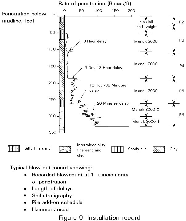
Some penetration under the self weight of the pile is normal. For soft soil conditions, particular measures are taken to avoid an uncontrolled run.
Piles are then driven or drilled until pile refusal.
Pile refusal is defined as the minimum rate of penetration beyond which further advancement of the pile is no longer achievable because of the time required and the possible damage to the pile or to the hammer. A widely accepted rate for defining refusal is 300 blows/foot (980 blows/metre).
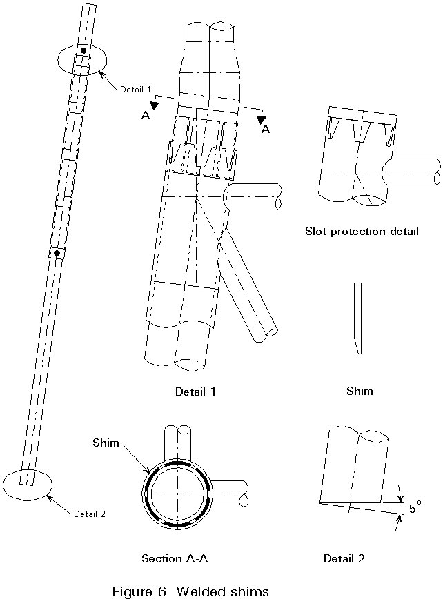
The shims are inserted at the top of the pile within the annulus between the pile and jacket leg (see Figure 6) and welded afterwards.
This metal-to-metal connection is achieved by a hydraulic swaging tool lowered inside the pile and expanding it into machined grooves provided in the sleeves at two or three elevations as shown on Figure 7.
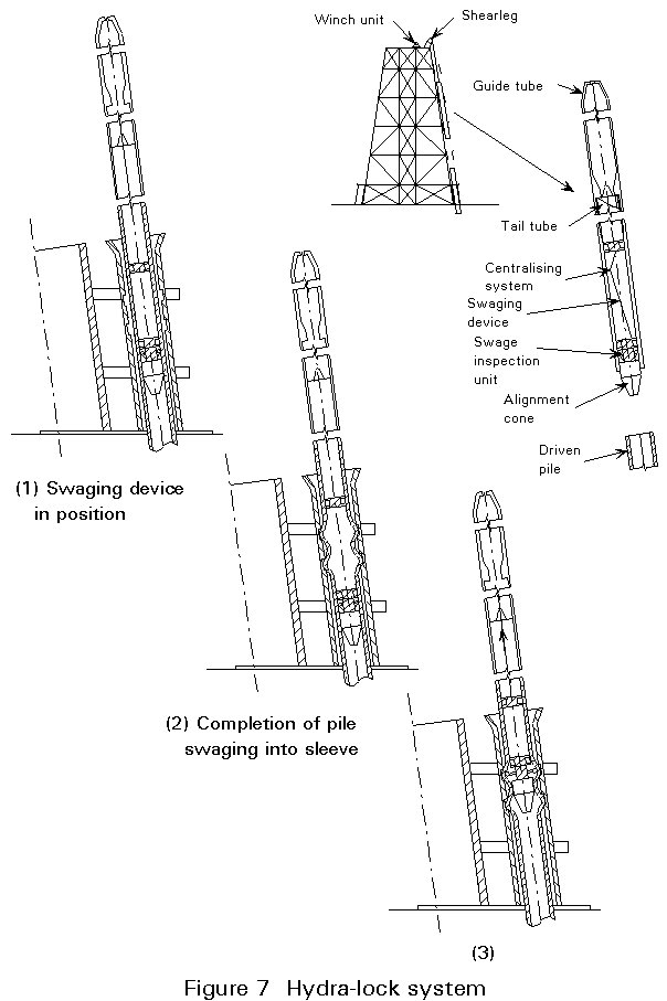
This type of connection is most popular for subsea templates. It offers immediate strength and the possibility to re-enter the connection should swaging prove incomplete.
This hybrid connection is the most commonly used for connecting piles to the main structure (in the mudline area). Forces are transmitted by shear through the grout.
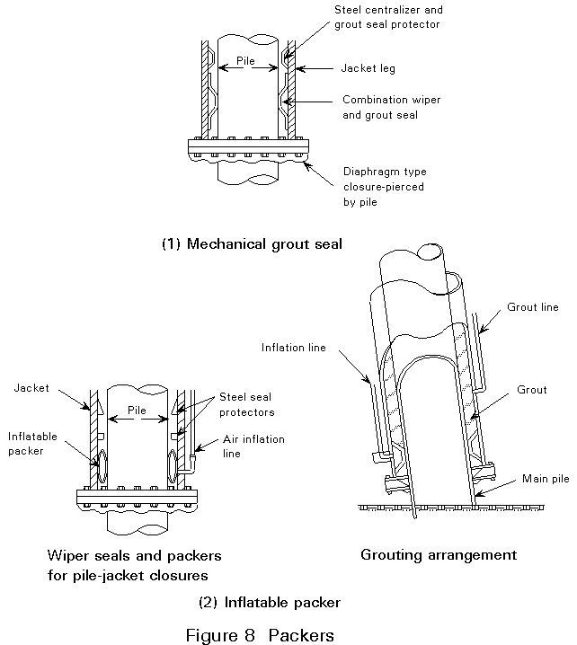
Figure 8 shows the two types of packers commonly used. The expansive, non-shrinking grout must fill completely the annulus between the pile and leg (or sleeve).
Bonding should be excellent; it is improved by shear connectors (shear keys, strips or weld beads disposed on the surface of the sleeve and pile in contact with the grout).
The width of the annulus between pile and sleeve should be maintained constant by use of centralizers and be limited to:
Packers are used to confine the grout and prevent it from escaping at the base of the sleeve. Packers are often damaged during piling and are therefore:
Thorough filling should be checked by suitable devices, e.g. electrical resistance gauges, radioactive tracers, well-logging devices or overflow pipes checked by divers.
Quality control shall:
The installation report shall mention:
- unexpected behaviour of the pile and/or hammer.
- interruptions of driving (with set-up time and blowcount subsequently required to break the pile loose).
- pile damage if any.
- equipment and procedure employed.
- overall volume of grout and quality.
- record of interruptions and delays.
Contingency documents should provide back-up solutions in case "unforeseen" events occur such as:
This lecture has described:
[1] API-RP2A, "Recommended Practice for Planning, Designing and Constructing Fixed Offshore Platforms", American Petroleum Institute, Washington, D.C., 18th ed., 1989.
|
A. Air/Steam Hammers |
|||||||||||||||||||
|
Make |
Model |
Rated Energy (ft-lbs) |
Ram Weight (kips) |
Max. Stroke (m) |
Std. Pilecap Weight (kips) |
Typical Hammer Weight (w/leads) (kips) |
Rated Operating Pressure (psi) |
Steam Consumption (lbs ht) |
Air Consumption (lbs ht) |
Hose ST/F ..... |
Rated BPM |
||||||||
|
Conmaco |
6850 5650 5300 300 200 |
510.000 325.000 150.000 90.000 60.000 |
85 65 30 30 20 |
72 60 60 36 36 |
57,5 59,0 12,7 12,7 12,7 |
312 262 92 86 74 |
180 160 160 150 120 |
31.500
8.064 6.944 5.563 |
7.500
1.711 1.471 1.195 |
2 @ 4 3 @ 4 4 3 3 |
40 45 46 54 59 |
||||||||
|
Menck (MRBS) |
12500 8800 8000 7000 5000 4600 3000 1800 850 |
1.582.220 954.750 867.960 632.885 542.470 499.070 325.480 189.850 93.340 |
275,58 194,01 176,37 154 110,23 101,41 66,14 38,58 18,96 |
69 59 59 49 59 59 59 59 50 |
154,32 103,62 85,98 92,4 66,14 52,91 33,07 22,05 11,5 |
853 600 564 583 335 313 205 125 64 |
171 150 142 156 150 142 142 142 142 |
53.910 32.400 30.860 30.800 20.940 19.840 12.130 7.060 3.530 |
26.500 16.700 15.900 14.830 10.400 9.900 6.000 3.700 1.950 |
2 @ 6 8 8 4 @ 4 6 6 5 4 3 |
36 36 38 35 40 42 42 44 45 |
||||||||
|
MKT |
OS-60 OS-40 OS-20 |
18.000 120.000 60.000 |
60 40 20 |
36 36 36 |
38,65 |
150 |
3 |
60 |
|||||||||||
|
C. Hydraulic Hammers |
|||||||||||||||||||
|
Make |
Model |
Rated Energy
(ft-lb) |
Ram Weight
(kips) |
Standard Pilecap Weight (kips) |
Hammer Weight
(kips) |
Typical Operating Pressure (psi) |
Rated Oil Flow (gal. min) |
Rated BPM |
|||||||||||
|
HMB |
4000 3000A 3000 1500 900 500 |
1.200.000 800.000 725.000 290.000 170.000 72.000 |
205 152 139 55 30,8 9,5 |
33 17,6
1,1 |
490 414
172 88 27,5 |
40-70 |
|||||||||||||
|
Menck |
MRBU MHU 1700 MHU 900 MH 195 MH 165 MH 145 MH 120 MH 96 MH 80 |
760.000 1.230.000 650.000 141.000 119.000 105.000 87.000 69.000 58.000 |
132 207 110 22,0 19,0 16,5 13,9 11,0 9,3 |
84 77
6,0 6,0 6,0 6,0 1,9 1,9 |
415 617 386 59 51 46 40 27 24 |
3400 3400 3100 3550 3190 2755 2320 2830 2465 |
845 845 580 98 103 102 103 75 75 |
50-80 32-65 48-65 38 42 42 44 48 48 |
|||||||||||
TABLE 1 Properties of some hammers used offshore
|
Hammer |
Type |
Blows per Minute |
Weight including Offshore Cage, if any (metric tons) |
Rated Striking Energy |
Expected Net Energy (ft-lb x 1000) |
||
|
(ft-lb x 1000) |
KNm |
On Anvil |
On Pile |
||||
|
Vulcan 3250 |
Single-acting steam |
60 |
300 |
750 |
1040 |
673 |
600 |
|
HBM 3000 |
Hydraulic underwater |
50-60 |
175 |
1034 |
1430 |
542 |
542 |
|
HBM 3000 A |
Hydraulic underwater |
40-70 |
190 |
1100 |
1520 |
796 |
796 |
|
HBM 3000 P |
Slender hydraulic underwater |
40-70 |
170 |
1120 |
1550 |
800 |
800 |
|
Menck MHU 900 |
Slender hydraulic underwater |
48-65 |
135 |
- |
- |
651 |
618 |
|
Menck MRBS 8000 |
Single-acting steam |
38 |
280 |
868 |
1200 |
715 |
629 |
|
Vulcan 4250 |
Single-acting steam |
53 |
337 |
1000 |
1380 |
901 |
800 |
|
HBM 4000 |
Hydraulic underwater |
40-70 |
222 |
1700 |
2350 |
1157 |
1157 |
|
Vulcan 6300 |
Single-acting steam |
37 |
380 |
1800 |
2490 |
1697 |
1440 |
|
Menck MRBS 12500 |
Single-acting steam |
38 |
385 |
1582 |
2190 |
1384 |
1147 |
|
Menck MHU 1700 |
Slender hydraulic underwater |
32-65 |
235 |
- |
- |
1230 |
1169 |
|
IHC S-300 |
Slender hydraulic underwater |
40 |
30 |
220 |
300 |
- |
- |
|
IHC S-800 |
Slender hydraulic underwater |
40 |
80 |
580 |
800 |
- |
- |
|
IHC S-1600 |
Slender hydraulic underwater |
30 |
160 |
1160 |
1600 |
- |
- |
|
IHC S-2000 |
Slender hydraulic underwater |
- |
260 |
1449 |
2000 |
- |
- |
|
IHC S-2300 |
Slender hydraulic underwater |
- |
- |
1566 |
2300 |
- |
- |
TABLE 2 Large pile driving hammers
|
Pile Outer Diameter |
Wall Thickness |
Hammer Energy |
|||
|
(in.) |
(mm) |
(in.) |
(mm) |
(ft-lb) |
(kN-m) |
|
24 30 36 42 48 60 72 84 96 108 120 |
600 750 900 1.050 1.200 1.500 1.800 2.100 2.400 2.700 3.000 |
5/8 - 7/8 ¾ 7/8 - 1 1 - 1¼ 17- 1¾ 17 - 1¾ 1¼ - 2 1¼ - 2 1¼ - 2 1½ - 2½ 1½ - 2½ |
15-21 19 21-25 25-32 28-44 28-44 32-50 32-50 32-50 37-62 37-62 |
50.000 - 120.000 50.000 - 120.000 50.000 - 180.000 60.000 - 300.000 90.000 - 500.000 90.000 - 500.000 120.000 - 700.000 180.000 - 1.000.000 180.000 - 1.000.000 300.000 - 1.000.000 300.000 - 1.000.000 |
70 - 168 70 - 168 70 - 252 84 - 120 126 - 700 126 - 700 168 - 980 252 - 1.400 252 - 1.400 420 - 1.400 420 - 1.400 |
Note 1: With the heavier hammers in the range given, the wall thicknesses must be near the upper range of those listed in order to prevent overstress (yielding) in the pile under hard driving.
Note 2: With diesel hammers, the effective hammer energy is from one-half to two-thirds the values generally listed by the manufacturers and the above table must be adjusted accordingly. Diesel hammers would normally only be used on 36-in. or less diameter piles.
Note 3: Hydraulic hammers have a more sustained blow, and hence the above table can be modified to fit the stress wave pattern.
TABLE 3 Typical values of pile sizes, wall thickness and hammer energies