Previous | Next | Contents
ESDEP WG 17
SEISMIC DESIGN
Lecture 17.5: Requirements and Verification
of Seismic Resistant Structures
OBJECTIVE/SCOPE
To present the general design principles and requirements for building structures in seismic zones.
PREREQUISITES
None.
RELATED LECTURES
None.
SUMMARY
The general principles (symmetry, regularity, redundancy, torsional resistance, diaphragms, ...) of an earthquake resistant design are first discussed.
Complete details on structural design for steel buildings, based on the general principles and including rules and checks of Eurocode
8 [1] are given. They include data on regularity, elements and connections, typology of structures and the q factors, strength and ductility checks required for elements and connections.
Overview of the requirements
Designing a safe structure in earthquake regions is a multi-planar problem. The following table summarizes the main requirements and criteria.
|
REQUIREMENTS |
CRITERIA |
|
Ultimate limit states
No collapse under
strong earthquake |
- checks on resistance, stability and ductility of structural elements
- overall stability of structure
- foundations |
|
Serviceability limit states
Limitation of damage under
moderate earthquake |
- checks on deformation conditions |
|
Other specific aseismic measures |
- planning and design
- height and other limitations
- foundations
- quality plan
- ground investigations |
Ultimate Limit State
For all structural elements, the design resistance Rd/gRd
³ design action effects Sd.
The resistance Rd is calculated according to rules specific to the material. Explanations are given in Sections 3 and 4.
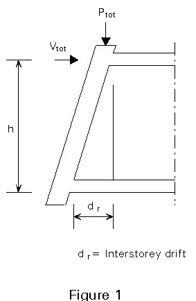
Second order effects, are either taken into account explicitly, or they are checked as being negligible using the following criterion (Figure 1).
M2nd order << M1st order
Ptot . dr << Vtot . h
q = 
where
Ptot is the total gravity load at and above the storey considered
dr is the design interstorey drift (dr = q . de !)
Vtot is the total seismic design shear at the storey considered
h is the storey height.
Checks on ductility are material related and are described in Sections 3 and 4.
The resistance of soil must satisfy "capacity design" requirements; this means that the foundations must resist the maximum forces that the structural elements can transmit to them, regardless of the actual values due to the seismic design actions.
Serviceability Limit State
Checks on deformation conditions
For structures including non-structural elements sensitive to deformation, the interstory drift dr is limited, e.g. 0,002h.
Joints between structures must be designed to avoid pounding between two adjacent structures.
Introduction
Some general principles for the design of structures to be erected in earthquake areas are given here. It should be pointed out that earthquake resistant structures can be designed without consideration to these principles.
Compliance with these principles will however substantially reduce the possibility of the occurrence of dynamic effects which cannot be predicted by linear analysis. For this reason, Eurocode
8 [1] prescribes lower values of seismic actions (higher q factors) for systems complying with the general rules. The overcost of an earthquake resistant structure is reduced by use of these lower values in comparison with a usual structure. It also seems that the combination "good design - simple analysis" gives safer structures than the combination "bad design - refined analysis".
Principle 1 - Simplicity
The dynamic behaviour of a simple structure is easy to understand and to compute. The risk of forgetting any special aspect of performance such as an interaction of parts with different rigidity is low. Overall simplicity leads to simple detailing.
Principle 2 - Continuity and uniform distribution of strength
Any discontinuity in the design brings a stress concentration and, potentially, a local failure mechanism. Energy dissipation in the structure should be as high as possible. There should therefore be many dissipative zones in the structure. As a result a global failure mechanism should be aimed at. The non-homogeneous behaviour of a structure with major discontinuity leads to tedious calculations and difficult design of the connection areas.
Practical continuity has many aspects.
Detailing:
- There should be no weakening in sections.
- Secondary effects generated by offsets, as well as sudden changes in sections should be avoided.
- Connections should be away from dissipative zones.
- Site control should be effective to obtain a proper correspondence between design and execution. Particular attention should be given to, for example, bolts, prestressing (minimum and maximum yield strength, ductility of the material), no locking of the displacement of the structure by unplanned infilled walls.
- There should always be positive links. Friction cannot be relied on to resist horizontal forces or relative displacements of, for example, supports, diaphragms, girders of a bridge. Similarly, gravity force is not enough to restrain non-structural elements. Disconnection of hanging ceilings or claddings can be dramatic.
Overall design:
Redundancy is a minimum condition for developing real continuity in a structure. It is essential, but not sufficient.
Continuity and uniform distribution of strength in the horizontal direction of a building generally means symmetry, if possible almost axisymmetry. Plan layout of vertical resisting elements should also recognise the need of a high global torsional stiffness. Major damage has been observed in the connection zones of structures with
'wings'. The differences in flexural mode shapes of these 'wings' induce this result, Figure 2.
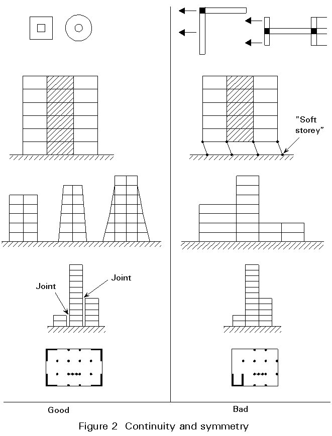
Continuity in the vertical direction means a lack of setbacks and a relatively uniform distribution of the shear and flexural resistance of the structure. The so-called "soft storey" should be avoided. Unintended changes in rigidity caused by "non-structural" elements like infills, partition walls ... should also be avoided, Figure 2. Eurocode 8 allows simplified methods of analysis of buildings when certain conditions are met, see Table 1.
|
Table 1: Structural regularity in Eurocode 8
For the application of simplified methods of analysis, a building can be classified as regular when the following conditions are satisfied simultaneously. |
|
Geometrical and structural layout in plan
× The plan configuration does not present divided shapes nor large recesses. When re-entrant corners or recesses exist their dimension does not exceed 25% of the building external dimension in the corresponding direction.
× The structure of the building is distributed along an orthogonal mesh defining two main directions with similar stiffnesses.
× The building has an approximately symmetrical plan configuration with respect to those two main orthogonal directions.
× At any storey the distances (measured in the two main directions) between the centre of masses and the centre of stiffness do not exceed 15% of the "resilience radius" defined as the square root of the ratio of the storey torsional and translational stiffnesses.
× The in-plan stiffness of the floors is high enough, in comparison with that of the vertical structural elements, such that a rigid behaviour may be assumed. Furthermore, the floors should not present large holes hindering such assumption especially if they are located in the vicinity of the main vertical structural elements. |
|
Vertical configuration
× The stiffness and mass properties are approximately uniform throughout the building height.
× Where there is a gradual setback throughout the height, the setback at any floor is not greater than 20% of the previous plan dimension in the direction of the setback and symmetry about the vertical axis is preserved.
× If a setback greater than 20%, but not greater than 50% and preserving symmetry, occurs within the lower 15% of the total height of the building above the surrounding ground level (or above the level of application of the seismic excitation), it may still be classified as regular. In such cases the structure of the base zone beneath a vertical projection of the upper storeys must be able to support at least 75% of the shear forces that would develop in that zone in a similar building without the base enlargement.
× Where setbacks occur only in one facade, the overall setback (sum of setbacks at all storeys) is not greater than 30% of the plan dimension in the first storey and at any floor the individual setback is not greater than 10% of the previous plan dimension. |
When circumstances, e.g. the available site, aesthetics or use of the building, are such that structural continuity is not possible for the whole volume of the structure, the latter can be subdivided into smaller blocks. Structural continuity can then exist in each block, the blocks being linked by flexible footpaths. A proper distance computed as the sum of their maximum displacements must be left between two contiguous blocks to avoid pounding of the blocks when they are
excited by earthquake motion.
Principle 3 - Dissipative structures
Building structures able to dissipate energy are introduced and discussed in Lecture 17.4. Dissipative zones must be safe and numerous. This situation can be achieved in different ways, by adopting the design approaches based on the principles described below.
Principle 4 - Low slenderness
In general, the more slender a structure, the worse the overturning effect of an earthquake.
High slenderness may however be useful in some cases (see Principle 7).
Principle 5 - Torsional resistance
Earthquake action generates special torsional effects in structures, mainly because the resultant of inertia forces generated by the earthquake is applied at the mass centre M of each floor of the structure and the latter generally does not coincide with the torsion centre S of the earthquake resistant structure, Figure 3. The resultant force times the distance to that centre gives a torsional moment Mt. In multi-storey frames, the torsional moment from one particular floor is increased by the resulting moment of the floors above. In most structures, the approach to evaluate this torsional moment is partly rational (the distance between S and M) and partly statistical, because the load distribution in a structure is not well known at the design stage and changes through the life of the structure. Codes indicate how to evaluate this second term. A few structures are free of torsional effects
(axisymmetrical), e.g. water towers.
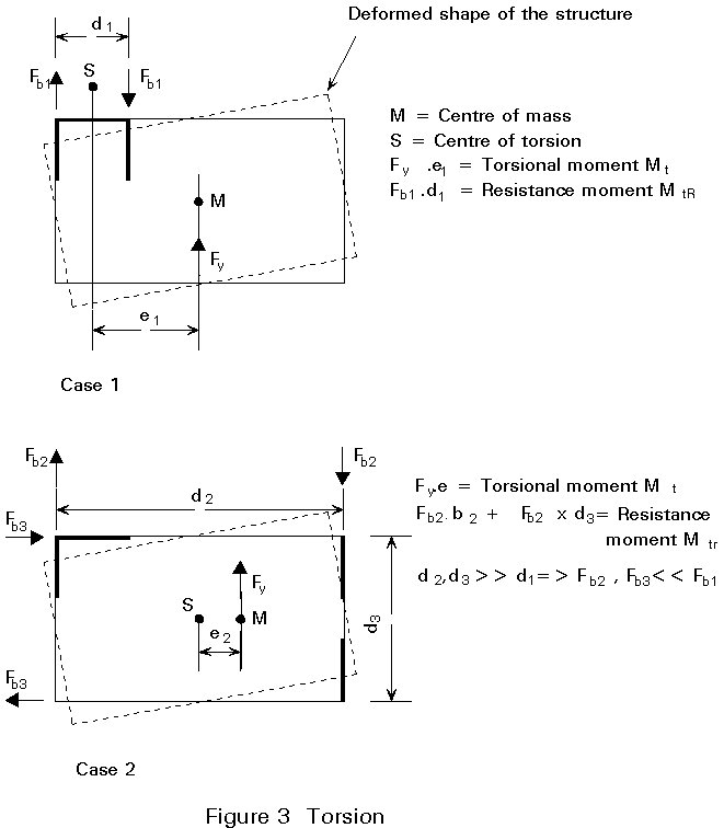
There may also be a second cause for torsional action. The earthquake itself results mainly in the vertical propagation of a shear wave so that two points of the structure may be moving differently at one time. This origin of torsion is normally important for structures which are very large in plan, e.g. bridges.
To resist the torsional action, the structure must be given adequate torsional rigidity. The best solution is obtained by putting the earthquake resistant part of structure close to the perimeter of the structure as a whole and all around it, complying with the symmetry principle. It must be pointed out that the classical "one vertical core" structure of earthquake free areas is not effective, because it lacks torsional rigidity. It should simply be avoided in unsymmetrical layouts.
Principle 6 - Diaphragms
Diaphragms in a building are the structures which transfer horizontal inertia forces, resulting from the motion applied to the masses of floors and their loading, towards the structures able to contain them.
Diaphragms must be structures of low deformability and capable of efficiently distributing the horizontal action between the various vertical resistant structures. Diaphragms may be provided in many ways: concrete slabs, composite slabs, trusses, frames. Diaphragms must be properly linked to the vertical rigidity elements. The links must be able to transmit the horizontal inertia force.
Principle 7 - Rational distribution of loads in the structure
Important loads should not be put at places where they generate inertia forces under earthquake loading. For example, a library should for preference be at ground level. An X-Ray installation should be close to the centre of rotation. Masses should be reduced whenever possible. For instance, using light floor systems rather than traditional slabs can bring drastic reductions in inertia forces and result in substantial economy in the framework. Similar choices should be made for partition walls, infills, claddings, etc.
Principle 8 - Stiffness adapted to the site
The shape of the design response spectrum (Lecture 17.4) indicates that earthquake forces are lower for structures characterized by a predominant high period (T) of vibration. This characteristic can sometimes be used at the start of a design, especially when more refined data are available for a particular site. For instance, in a site with thick alluvium layers, which is characterized by a response spectrum with relatively high amplitudes in the high period range and low amplitudes in the low period range, a very rigid structure would better fit than a flexible one. The opposite choice would apply to rock areas.
Principle 9 - A strict correspondence between the real structure and the model used in its analysis
Designing a structure which is safe under earthquake loading is feasible. However to achieve a safe structure, the model used in the analysis must correspond to the real structure. Otherwise, for instance, yielding will take place in other places than foreseen or will not take place and be replaced by a brittle failure. In earthquake engineering more material or a stronger material does not mean more safety, because safety is not only derived from strength, but also from ductility.
There are many causes for discrepancies between reality and model, for example:
- non-structural elements like infills must not give unexpected rigidity to a structure. Such rigidity can completely change the behaviour of the structure, introduced high local shear and cause failure. Non-structural elements must be linked in a way such that they do not in fact play any structural role.
- distribution of yield strength throughout the structure should not differ much from that assumed, otherwise yielding will take place elsewhere than foreseen or not take place.
- site control should ensure the real structure corresponds to that planned.
Materials
Materials such as structural sections, bolts and welds which are used for steel structures in earthquake prone regions are not different from those used for steel structures elsewhere. They are usually submitted to the same quality checks.
However, compliance to Principle 9 of Section 2 requires the definition by the designer of a maximum value of yield strength of the steel to be used in the structure. This requirement is specific to earthquake resistant design. The reason is that normally steel material is delivered on the basis of a guaranteed minimum yield strength, but in practice it may have a far higher value of yield strength than that ordered. This fact leads in general to conservative design which is not detrimental for normal steel structures, but which can be harmful in the case of earthquake resistant steel structures. Overstrength effects in dissipative parts of the structure can lead to a concentration of seismic energy dissipation at points where it is not expected nor wanted, as for instance at the connections.
Therefore, for the dissipative parts of the structure both lower and upper values of yield strength are specified in design and in ordering of the material. Moreover, sufficient control to avoid overstrength must be undertaken through specific application rules.
General structural steels according to EN 10025 are used in earthquake resistant steel structures. Bolts should preferably be high strength grades 8.8 and 10.9.
Sections
Steel sections in dissipative zones of the structure must be able to withstand yielding without significant loss of bearing resistance. This requirement can be a problem in compressed parts of sections where early local buckling can occur. To avoid local buckling, restrictions are placed on the width-to-thickness ration b/t of the compressed flat parts of sections. These restrictions depend on the maximum intended overall ductility of the structure. For this reason, steel sections are classified into three classes in accordance with three levels of behaviour factor q, as indicated in the following table.
|
Behaviour factor q |
Section class |
|
q < 4
2 < q £ 4
q £ 2 |
1
2
3 |
The limiting values b/t for the above three classes of section are given in
Eurocode 3 [2].
An increase of ratio b/t results in a lower local ductility because of the appearance of local buckling. This reduction therefore results in a reduction of the capacity of the structure to dissipate energy, which is finally expressed by a smaller value of the behaviour factor q.
Connections
Connections should not be the location for failure, for the following reasons:
- their failure mechanism is generally not well known.
- they have low global ductility, because stress concentrations locally exhaust the available ductility of the material.
- high strength bolts are not very ductile. In tension connections they may be subjected additionally to prying forces which are also not well known.
- the heat affected zone close to welds is less ductile than the original material.
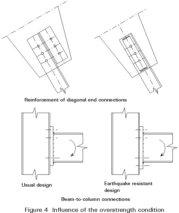
Therefore, a criterion is imposed according to which connections near dissipative zones of the structure must have sufficient overstrength so that yielding occurs in the ductile members (overstrength criterion).
Welded connections made with full penetration butt welds are considered to satisfy the above criterion.
Welded connections made with fillet welds and bolted connections, in order to satisfy the above overstrength criterion, must meet the following requirements:
Rd ³ 1,20 Rfy
where
Rd is the design resistance of the connection
Rfy is the yielding resistance of the connected member.
The above condition can often be attained by an increase of the member section in the connection zone. Figure 4 shows two bracing connections, where the fulfilment of the overstrength condition requires a reinforcement of the connection zone either by a welded plate or by an additional bolted cleat.
In bolted connections, the failure of bolts in bearing must control the behaviour and not failure in shear.
From the above discussion it is evident that the overstrength condition can lead to expensive connections. There are two possible ways to overcome this overstrength penalty:
- to use full penetration butt weld connections in dissipative zones.
- to reduce the member section and consequently the yielding resistance of the dissipative zone so that the overstrength condition gives a less penalizing value of Rd.
Earthquake resistant structures - General considerations
The term "earthquake resistant structures" (ERS) refers to those structural systems of a building which are designed to resist the horizontal seismic actions.
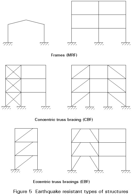
In dissipative steel ERS, i.e. structures which through inelastic hysteretic behaviour can be submitted to considerable deformations without failure by dissipating large amounts of seismic energy, there are essentially three structural systems used to resist horizontal seismic actions (Figure 5):
a. Moment resistant frames (MRF) or simple frames.
b. Concentrically braced frames (CBF) or concentric truss bracings.
c. Eccentrically braced frames (EBF) or eccentric truss bracings.
In general, frames are more flexible than braced truss structures. Therefore they may experience greater horizontal displacements under equal seismic actions. Such displacements can be a problem with respect to the "P-D effect" under a strong earthquake or to "damage" under a moderate earthquake. Compliance with the overstrength criterion may also be very expensive for members in bending.
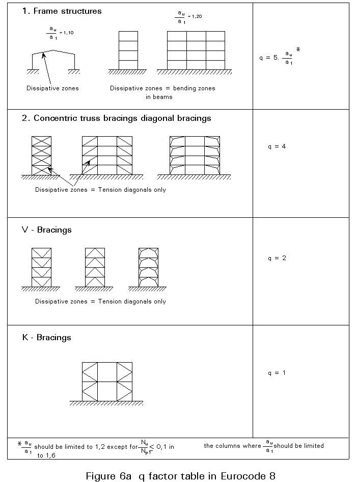
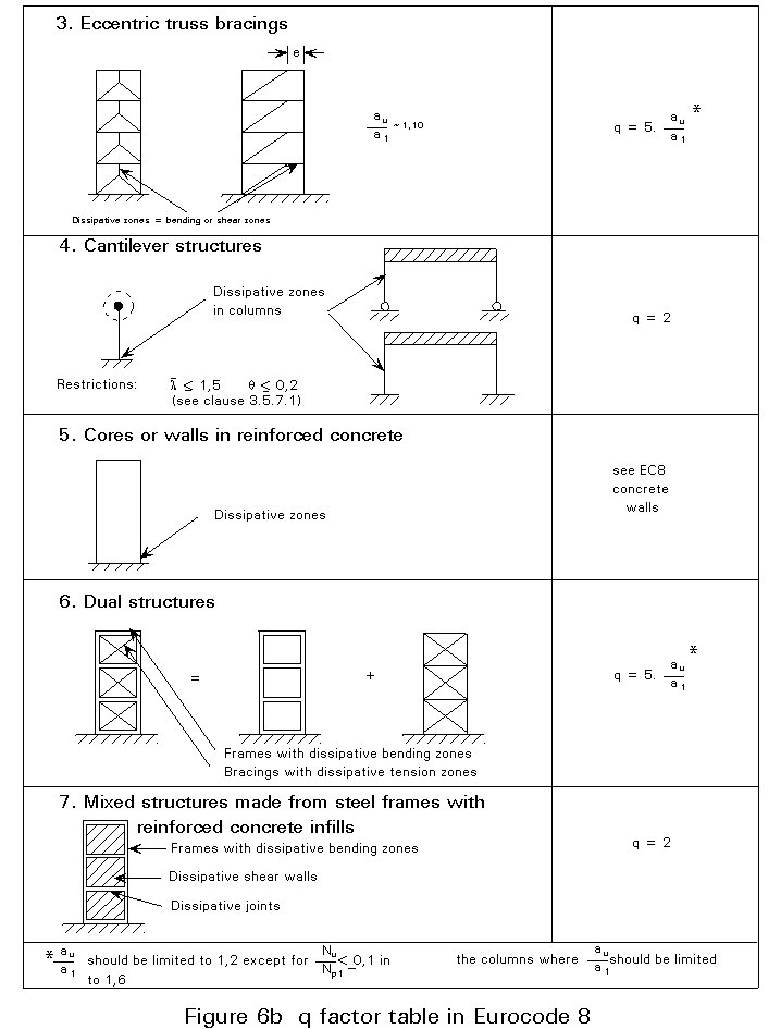
Truss braced structure contrary to frames, are always stiff depending of course on their configuration. Their capacity to dissipate seismic energy differs greatly from one type to the other. The ability of both frames and truss structures to dissipate energy whilst resisting seismic action is quantified by the value of the behaviour factor "q", which has been described in Lecture 17.4.
Figure 6 presents the values of q-factor for the various systems provided that regularity criteria are met. If the building is not regular in elevation the listed q values shall be reduced by 20%. These values should be considered as maximum allowable ones, even if in some cases direct dynamic non-linear analysis indicates higher q values in the region of 10 or 12.
Earthquake resistant structures
Specific considerations - criteria according to Eurocode 8
Frames
Frames are structures that resist horizontal seismic actions mainly through bending of their members. They have a large number of energy dissipative zones located near to the beam-to-column connections. The energy is dissipated through cyclic bending behaviour.
During seismic design, it is assumed that the frame as a whole satisfies the basic criterion of avoiding the creation of a soft storey.
Under this criterion, the aim is to form plastic hinges in the beams and not in the columns in a global failure mechanism, except at the bases of the columns. This mechanism is the so-called "strong columns-weak beams" concept
(Figure 7). When the design is such that plastic hinges form in the beams rather than in the columns, these hinges have the role of spreading yield through the structure. Moreover, the P-D effect is reduced and interaction between axial force and biaxial bending moments in the columns is avoided.
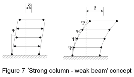
The concept of "strong columns-weak beams" is not applied to single storey frames, to the top floor of multi-storey frames and at the base of columns where they are connected to foundations.
Beams
Beams are verified as having sufficient safety against lateral or lateral and torsional buckling failure.
To obtain safe plastic hinges in the beams, a check is made that the full plastic moment resistance and rotation capacity are not decreased by compression and shear forces. To this end the following inequalities are verified at the location where the formation of hinges is expected.


where
M and N are the seismic action effects taking account of the behaviour factor q
Mpd, Npd and Vpd are the ultimate resistances of the section at the plastic hinge
Vo is the shear force of the beam, considered as simply supported, due to vertical loads
VM = (MRA + MRB)/1 is the shear force due to the resisting moments MRA and MRB of the beam at its extremities A and B, calculated with the upper value of yield strength.
Beam-to-column connections must satisfy the requirements for connections, considering the bending resistance Mpd of the plastic hinge section, and shear force equal to (Vo + VM), as specified above.
Columns
Columns are verified in axial force and bending, the design values of bending moments MCD,c being resistance design values, i.e. values derived from maximum design moments of column due to seismic actions, multiplied by a suitable capacity amplification factor.
The most unfavourable shear force of the column due to seismic combination actions must respect the following condition:
V/Vpd = < 0,5
The transmission of forces between beam flanges at a beam-column node is achieved by extending beam flanges to stiffeners across the column.
Concentric truss bracings
General
In concentric truss bracings horizontal seismic forces are mainly resisted by members in axial loading (tension or compression). In such systems ductile members are mainly the tension braces, because energy dissipation in compression braces deteriorates quickly due to buckling. The usual types of concentric truss bracings are the following:
Diagonal type
The alternating horizontal forces are resisted in this type by the corresponding tension braces only, while the contribution of compression braces is neglected. The diagonal braces of alternating loading can be in the same bay (X bracing) or in different bays of the same storey. In the latter case the quantity "Acosq " (where A is the area of the brace section and q is the slope to the horizontal) must not vary by more than 10% between two opposite braces in the same storey.
Type V or L
In this type both tension and compression braces are needed to resist the horizontal seismic forces (for equilibrium reasons). The diagonal braces may have a V shape or a L shape, in which case they meet at the middle of the upper beam without interrupting its continuity.
Type K
Bracings of this type, where the meeting point of diagonals intersects the column at an intermediate point, do not offer any possibility of ductile behaviour because they demand the participation of the column in the yielding mechanism. Therefore q = 1 for this type of bracing, and its use is not recommended.
Diagonals
Diagonals must be verified for the condition: N/Npd £ 1,0
where
N is the maximum tensile force due to seismic combination actions
Npd is the design resistance in tension
Satisfactory dissipative behaviour of diagonals depends on their slenderness. For this reason the following condition must be satisfied:
 =
=  £ 1,5
£ 1,5
where
is the effective slenderness of the diagonal
A is the cross section area
fy is the yield strength
Ncr is the ideal critical Euler load of the diagonal (= p2EI/12).
Note: The above condition
£ 1,5 is equivalent to slenderness ratio l £ 140 for steel Fe E 235, and l £ 114 for steel FE E 355.
Columns and beams
Columns and beams are capacity designed, i.e. they are verified for buckling under an axial load acd N, where N is the maximum axial load due to seismic combination actions and acd is a suitable amplification factor.
In bracings of type V or L the horizontal beams are designed to resist their vertical loads, neglecting the intermediate support provided by the diagonals.
Eccentric truss bracings
General
Eccentric truss bracings are a lateral load-resisting system for steel buildings which can be considered a hybrid between conventional frames and concentric truss bracings. They combine most of individual advantages of frames and concentric bracings, whilst they minimize their respective disadvantages.
Figure 8 illustrates some common arrangements.
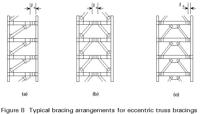
The main characteristic of eccentric truss bracings is that at least one end of every brace is connected in such a way that the brace force is transmitted either to another brace or to a column through shear and bending in a beam segment called a "link", denoted by the symbol 1s. Because shear and bending in the link due to horizontal forces are of considerable magnitude, it is convenient to concentrate the ductility requirements to that segment.
The most attractive feature of eccentric truss bracings for seismic-resistant design is their high stiffness combined with excellent ductility and energy dissipation capacity.
The yielding mechanism of links depends on the ratio of 1s to the length 1o=2Mp/Vp where Mp and Vp are the plastic strengths in bending and shear of the link. Theoretically if 1s/1o £ 1,0 the links yield in shear (shear plastic hinge). However, experiments have shown that the effect of strain hardening is very important and cannot be neglected. As a result, in order to assure the more desirable behaviour of links that yield in shear, it is recommended that 1s/1o£ 0,8. When 1s/1o ³ 1,3 the link yields in bending (moment plastic hinges). Yielding of the link is mixed between the above two limits. In all cases there is a possibility for adequate ductility.
Links are designed to provide enough ductility. The other members (bracings, columns and rest length of beams) are capacity designed, so that yielding is confined to the links.
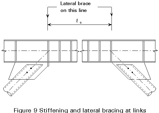
Links
Key elements in developing the full strength and rotation capacity of shear links are proper stiffening and lateral bracing. Two-sided, full-depth stiffeners must be provided at the link end. Intermediate stiffeners may be single sided for beam depths less than 600 mm, but are required on both sides of the web for deeper beams.
The maximum distance between successive stiffeners is taken equal to 56tw-d/5 for 1s/1o ³ 1,15 or equal to 38tw - d/5 for 1s/1o £ 0,80. For intermediate values of 1s/1o a linear interpolation is made.
Lateral bracing must be provided at the link ends at the locations shown in
Figure 9. Strong and stiff lateral bracing at these locations is critical to the stability of both the link and the brace. A composite deck by itself cannot be counted upon to provide adequate lateral support for the link ends. Transverse beams are the preferred lateral-bracing system.
After the selection of the link section, all other truss members are designed to remain essentially elastic under the forces generated by the fully yielded and strain-hardened link. This design requires an estimate of the ultimate shear force that can be achieved by the link. The ultimate shear force should be taken at least as:
Vult = 1,5 Vp
Columns and braces
Columns must be designed to remain essentially elastic under the ultimate link forces, as well as the appropriate vertical load contributions.
Braces must not buckle. They are therefore designed for the axial forces generated by the ultimate link shear given above. Experimental results show that ultimate link shear forces may sometimes exceed the value of 1,5 Vp due to overstrength of the web or due to the presence of a thick composite concrete deck. A conservative design of the bracings is therefore appropriate.
Diaphragms
The horizontal diaphragms and bracings must be able to transmit with sufficient overstrength the earthquake forces to the various earthquake-resistant elements connected by them.
This condition is assumed to be fulfilled by using a magnification factor of 1,5 for the verification forces obtained from the analysis. Eurocode
8 [1] also gives minimum detailing rules for diaphragms in reinforced concrete.
Specific control measures
The details of connections, sizes and qualities of bolts and welds as well as the steel grade of the members and the allowable maximum yield strength fy in the dissipative zones are indicated on the fabrication and erection drawings.
At the different phases of fabrication and construction continuous checks are necessary in order:
- to guarantee that the specified maximum yield strength of steel is not exceeded by more than 10%.
- to guarantee that the distribution of yield strength throughout the structure does not substantially differ from the distribution assumed in the design. This check aims at the achievement of sufficient regularity in terms of yielding behaviour to prevent the energy dissipation from being concentrated to one storey only (Figure 10).
- to guarantee that the stiffness and strength assumed in the design are not exceeded by more than 10%.
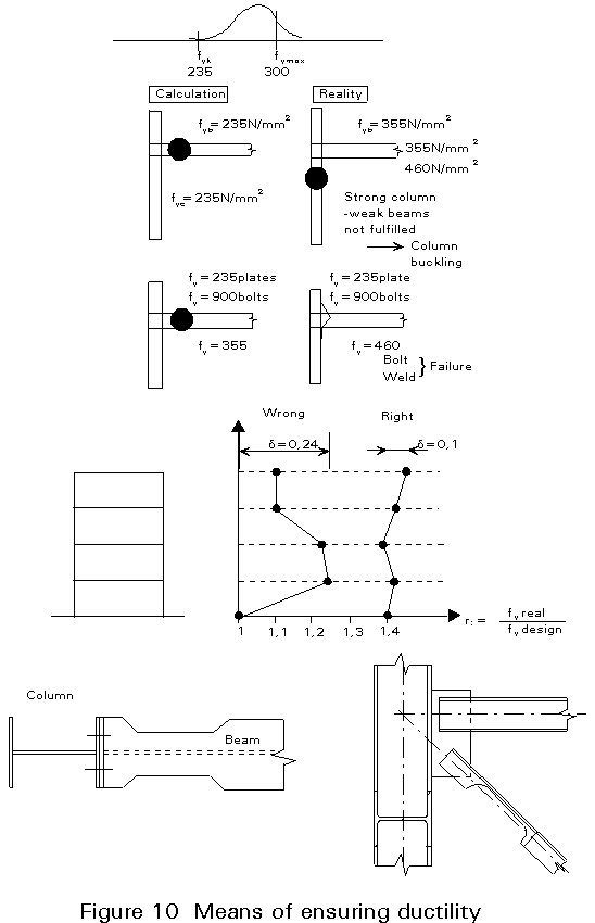
Whenever one of the above criteria is not fulfilled, either new computations of the structure and of its details are made to demonstrate its efficiency, or changes are made to confer equivalent efficiency. For instance, such a change could be the reduction of the member section so that its plastic resistance is equal to the intended one (Figure 10). A change of this kind allows more reasonable dimensions of the connection (end plates, bolts) since in the overstrength condition of connections Rfy is reduced because it refers to the reduced section which becomes the dissipative zone.
|
Cross-section and boundary condition |
Stress distribution
(compression positive) |
Class A |
Class B |
Class C |
|
Rectangular hollow section |
Compression |
33 e |
37 e |
41 e |
|
Tubular section |
Compression |
50 e2 |
70 e2 |
85 e2 |
|
Webs of I-profiles
Webs of flanges of welded sections |
plastic
elastic
distribution distribution |
66 e |
78 e |
90 e |
|
Compression
|
33 e |
39 e |
41 e |
|
Combined bending and compression
plastic elastic
distribution distribution |

|

|

|
|
Outstanding flanges of welded box sections or flanges of I-Profiles |
Compression |
9 e |
10 e |
12 e |
|
Combined bending and compression
|

|

|

|
|
Combined bending and compression |

|

|

|
|
Flanges of
I-Profiles |
Compression |
20 e |
22 e |
26 e |
|
General
e =  |
fy |
235 |
275 |
355 |
|
e |
1 |
0,92 |
0,81 |
Table 2 Limit b/t ratio of compressed parts of cross-sections for different cross-sectional classes
- The main requirements for the design of a structure in earthquake regions are that it shall not collapse under a strong earthquake and that damage is limited under a moderate earthquake.
- To meet these requirements design is based on general principles usually involving:
× simplicity
× continuity and uniform distribution of strength
× ability to dissipate energy
× avoidance of high slenderness
× torsional resistance
× stiffness adapted to the site
× correspondence between the real structure and the model used in its analysis.
Rules and checks are given in Eurocode 8 [1] based on these general principles covering materials, sections, connections and the structural systems which provide earthquake resistance. Particularly considerations relate to frames, beams, columns and truss bracings.
[1] Eurocode 8: "Structures in Seismic Regions - Design", CEN (in preparation).
[2] Eurocode 3: "Design of Steel Structures": ENV 1993-1-1: Part 1.1: General rules and rules building, CEN, 1992.
- ECCS-CECM-EKS: "European Recommendations for Steel Structures in Seismic Zones", Technical Working Group 1.3: Seismic Design, N.54, 1988.
- SEAOC: "Recommended Lateral Force Requirements and Commentary", 1990.
- Popov, E. P. and Engelhardt, M. D., Seismic Eccentrically Braced Frames, USA.
Previous | Next | Contents